БЛОК АВТОМАТИЧЕСКОЙ ТРАНСМИССИИ ПОВТОРНАЯ СБОРКА

-
BEARING POSITION
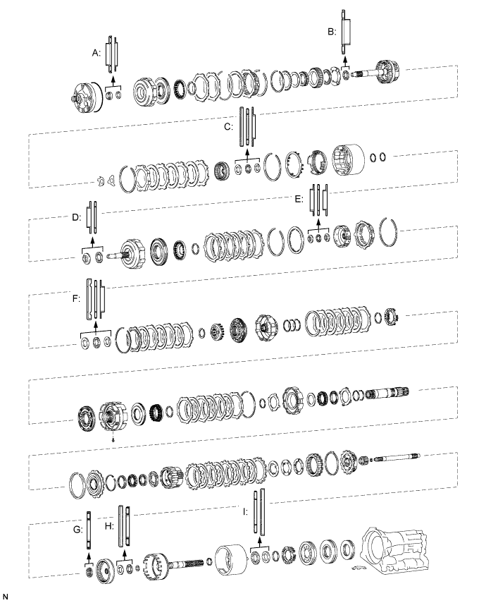
Bearing and Race Diameter Position Front Race Diameter Inside/Outside Thrust Bearing Diameter Inside/Outside Rear Race Diameter Inside/Outside A - 24.32 mm (0.957 in.)/43.20 mm (1.70 in.) 24.32 mm (0.957 in.)/39.20 mm (1.54 in.) B - 37.30 mm (1.47 in.)/52.52 mm (2.07 in.) - C 30.00 mm (1.18 in.)/48.54 mm (1.91 in.) 28.30 mm (1.11 in.)/46.48 mm (1.83 in.) 27.58 mm (1.09 in.)/44.70 mm (1.76 in.) D 24.05 mm (0.947 in.)/37.59 mm (1.48 in.) 23.34 mm (0.919 in.)/37.59 mm (1.48 in.) - E 24.05 mm (0.947 in.)/37.59 mm (1.48 in.) 23.34 mm (0.919 in.)/37.59 mm (1.48 in.) 21.41 mm (0.843 in.)/37.59 mm (1.48 in.) F 30.00 mm (1.18 in.)/47.9 mm (1.89 in.) 28.30 mm (1.11 in.)/46.48 mm (1.83 in.) 27.58 mm (1.09 in.)/44.70 mm (1.76 in.) G - 21.40 mm (0.843 in.)/47.30 mm (1.86 in.) - H 30.00 mm (1.18 in.)/48.54 mm (1.91 in.) 28.30 mm (1.11 in.)/46.48 mm (1.83 in.) - I - 38.15 mm (1.50 in.)/55.30 mm (2.18 in.) 39.12 mm (1.54 in.)/57.53 mm (2.26 in.) -
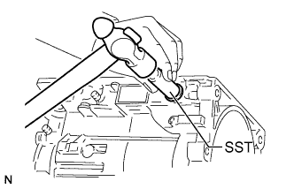
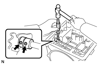
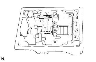
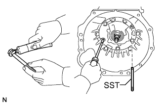
INSTALL MANUAL VALVE LEVER SHAFT OIL SEAL
-
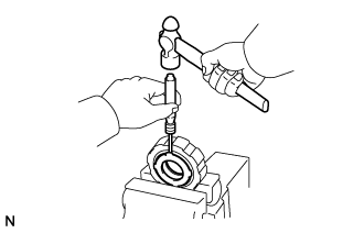
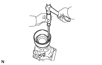
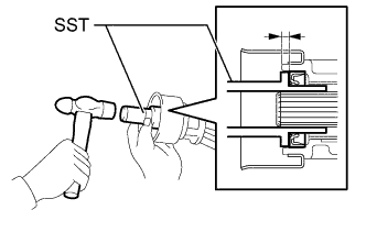
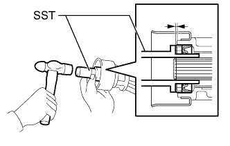
Using SST, tap in 2 new manual valve lever shaft oil seals.
- SST
- 09350-20015 ( 09361-30011 )
-
Coat the lips of the manual valve lever shaft oil seals with MP grease.
-
-
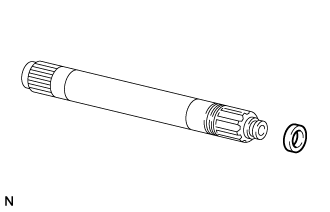
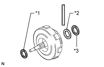
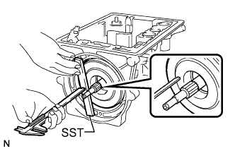
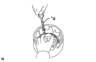
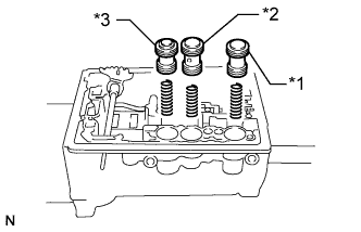
INSTALL MANUAL VALVE LEVER SHAFT
-
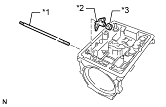
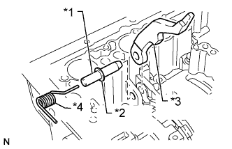
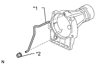
Text in Illustration *1 Manual Valve Lever Shaft *2 Manual Valve Lever *3 Spacer Install a new spacer to the manual valve lever.
-
Insert the manual valve lever shaft into the transmission case through the manual valve lever to install it.
-
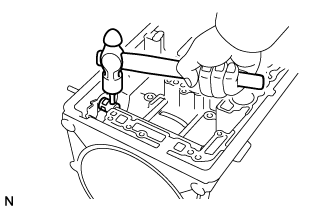
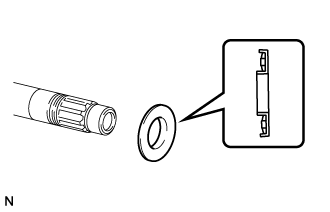
Using a hammer, tap in a new spring pin.
-
Align the manual valve lever indentation with the spacer hole, and stake them with a pin punch.
-
Check that the manual valve lever shaft rotates smoothly.
-
-
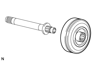
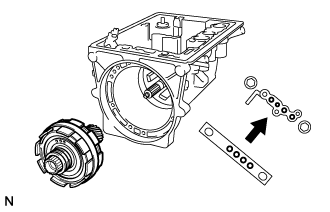
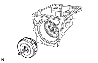
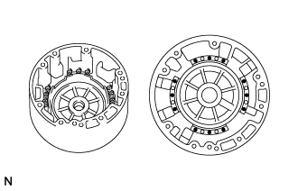
INSTALL NO. 3 BRAKE PISTON
-
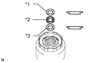
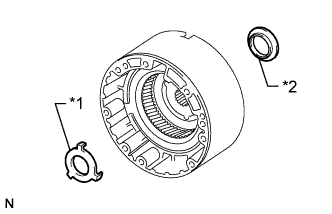
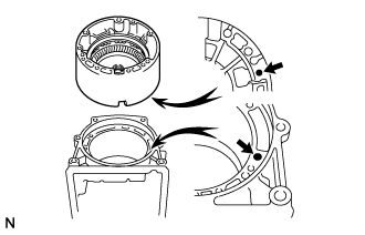
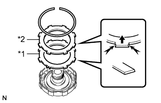
Text in Illustration *1 No. 3 Brake Piston *2 Brake Reaction Sleeve *3 Inner Piston Coat 5 new O-rings with ATF and install them to the inner piston, brake reaction sleeve and No. 3 brake piston.
Note
The thinner O-ring must be installed to the outside of the sleeve.
-
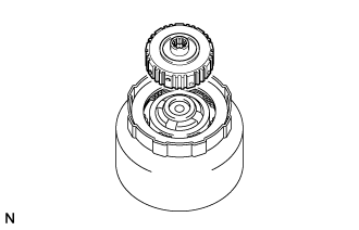
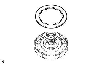
Assemble the inner piston, brake reaction sleeve and No. 3 brake piston.
-
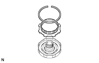
Press the assembled pistons into the transmission case by hand to install them.
Note
Be careful not to damage the O-rings.
-
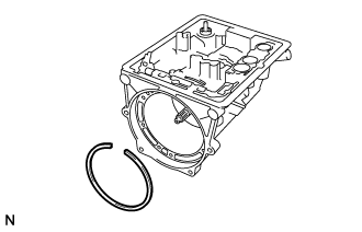
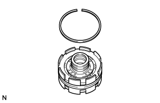
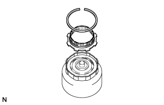
Make sure that the end gap of the snap ring is not aligned with the claw of the spring seat.
-
-
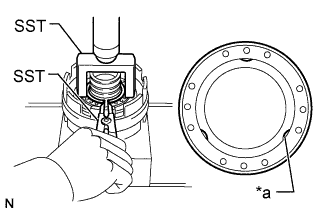
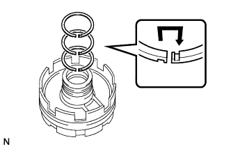
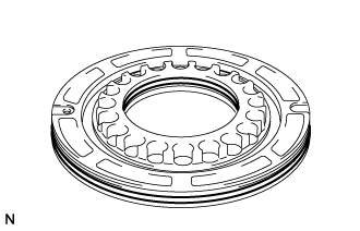
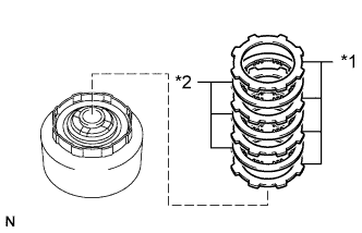
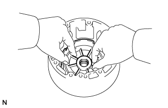
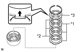
INSTALL NO. 3 BRAKE PISTON RETURN SPRING SUB-ASSEMBLY
-
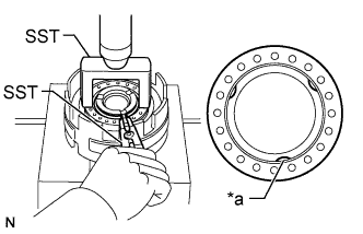
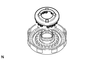
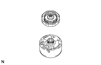
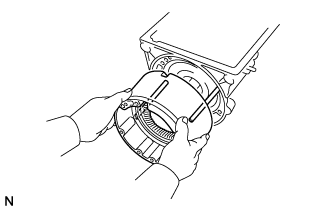
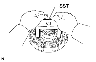
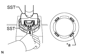
Place the No. 3 brake piston return spring sub-assembly onto the No. 3 brake piston.
-
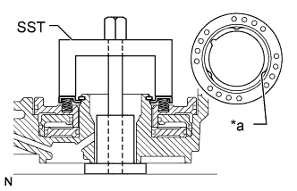
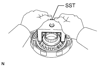
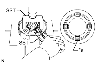
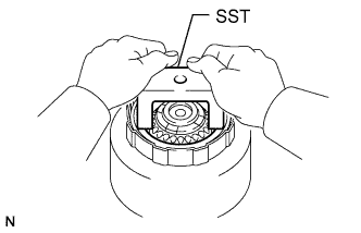
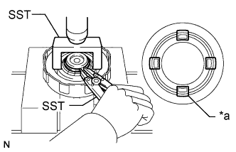
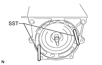
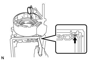
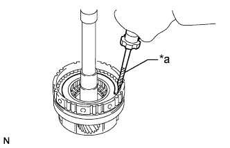
Text in Illustration *a Claw Position SST as shown in the illustration and compress the No. 3 brake piston return spring sub-assembly with SST.
- SST
- 09350-20015 ( 09369-20040 )
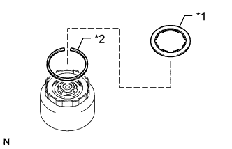
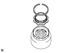
-
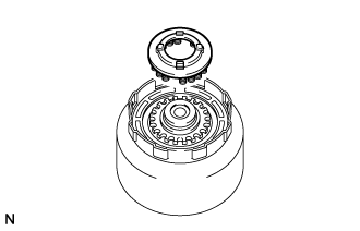
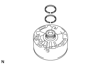
Install the snap ring with a snap ring expander.
Note
-
Make sure that the end gap of the snap ring is not aligned with the claw of the spring seat.
-
Do not expand the snap ring ends excessively.
-
Make sure that the snap ring is inserted into the groove.
-
-
-
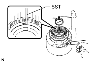
INSPECT NO. 3 BRAKE PISTON MOVEMENT
-
Check that the No. 3 brake pistons move smoothly when applying compressed air into and releasing compressed air from the transmission case.
-
-
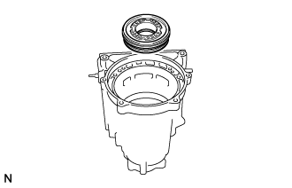
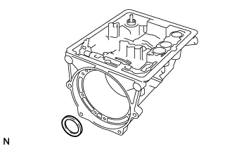
INSTALL BRAKE APPLY TUBE
-
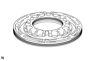
Coat the race with MP grease and install it to the transmission case.
Race Diameter Item Inside Outside Race I 39.12 mm (1.54 in.) 57.53 mm (2.26 in.) Note
Make sure the race is installed so that it is oriented correctly.
-
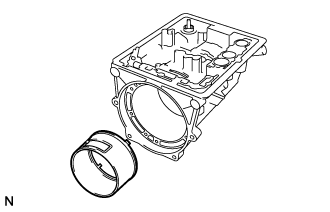
Align the locking tabs of the brake apply tube with the cutouts of the transmission case and install the brake apply tube.
Note
Make sure that the tabs of the brake apply tube end are completely inserted into the No. 3 brake piston.
-
-
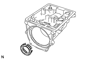
INSTALL BRAKE PLATE STOPPER SPRING
-
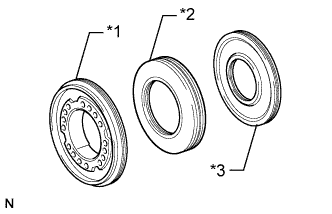
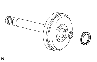
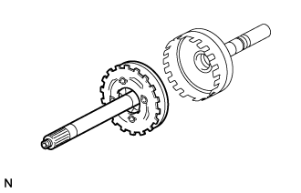
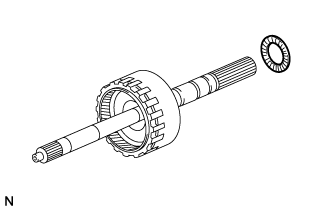
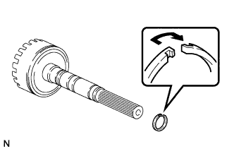
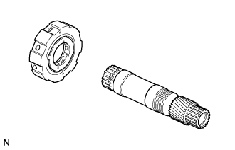
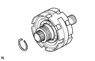
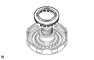
INSTALL REAR PLANETARY RING GEAR SUB-ASSEMBLY
-
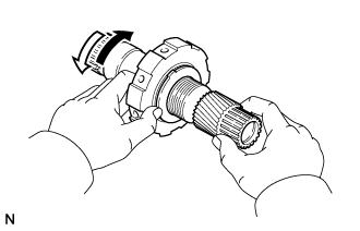
Coat a new oil seal ring with ATF and install it to the intermediate shaft sub-assembly.
Tech Tips
After installing the oil seal ring, check that it rotates smoothly.
-
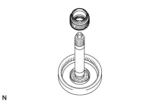
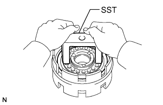
Coat the bearing with MP grease and install it to the intermediate shaft.
Bearing Diameter Item Inside Outside Bearing G 21.40 mm (0.843 in.) 47.30 mm (1.86 in.) Note
Make sure the bearing is installed so that it is oriented correctly.
-
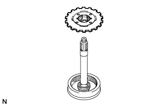
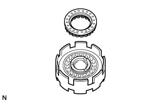
Install the ring gear to the intermediate shaft sub-assembly.
-
Install the set ring.
-
-
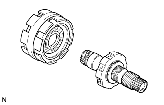
INSTALL REAR PLANETARY SUN GEAR
-
INSTALL REAR PLANETARY GEAR ASSEMBLY
-
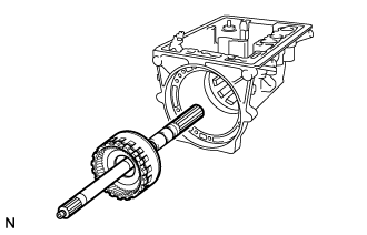
INSTALL INTERMEDIATE SHAFT SUB-ASSEMBLY WITH REAR PLANETARY GEAR ASSEMBLY AND REAR PLANETARY RING GEAR SUB-ASSEMBLY
-
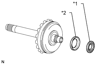
Text in Illustration *1 Bearing H *2 Race H Coat the bearing and race with MP grease and install them to the rear planetary ring gear sub-assembly.
Bearing and Race Diameter Item Inside Outside Race H 30.00 mm (1.18 in.) 48.54 mm (1.91 in.) Bearing H 28.30 mm (1.11 in.) 46.48 mm (1.83 in.) Note
Make sure the bearing and race are installed so that they are oriented correctly.
-
Install the intermediate shaft sub-assembly with rear planetary gear assembly and rear planetary ring gear sub-assembly to the output shaft assembly.
-
-
INSTALL FRONT PLANETARY RING GEAR
-
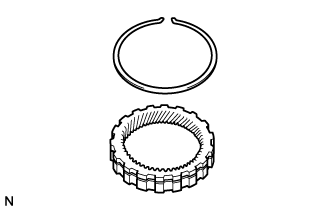
Install the snap ring.
Note
-
Do not expand the snap ring ends excessively.
-
Make sure that the snap ring is inserted into the groove.
-
-
Align the snap ring ends with the wide cutout portion of the output shaft assembly.
Note
Make sure that the snap ring is inserted into the groove.
-
Using a snap ring expander, install the front planetary ring gear while compressing the snap ring.
-
Check that the snap ring is installed to the groove of the output shaft assembly.
-
-
INSTALL REAR PLANETARY GEAR ASSEMBLY WITH INTERMEDIATE SHAFT SUB-ASSEMBLY
-
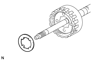
Coat the thrust washer with MP grease and install the thrust washer to the rear planetary gear assembly.
Note
Make sure that the tabs of the washer are aligned with the cutout portions on the rear planetary gear assembly.
-
Coat the bearing with MP grease and install it to the output shaft assembly.
Bearing Diameter Item Inside Outside Bearing I 38.15 mm (1.50 in.) 55.30 mm (2.18 in.) Note
Make sure the bearing is installed so that it is oriented correctly.
-
Coat the thrust washer with MP grease and install the thrust washer to the rear planetary gear assembly.
Note
Make sure that the tabs of the thrust washer are aligned with the cutout portions on the rear planetary gear assembly.
-
Coat a new oil seal ring with ATF.
-
Connect the ends of the oil seal ring and install it to the output shaft assembly.
Note
Do not expand the oil seal ring excessively.
Tech Tips
After installing the oil seal ring, check that it rotates smoothly.
-
Install the intermediate shaft sub-assembly with rear planetary gear assembly and output shaft assembly to the transmission case.
-
-
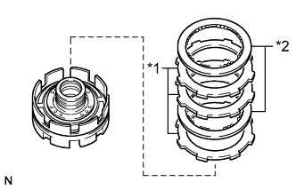
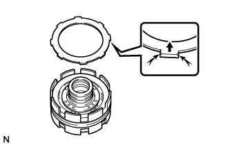
INSTALL NO. 3 BRAKE DISC SET
-
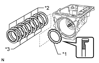
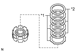
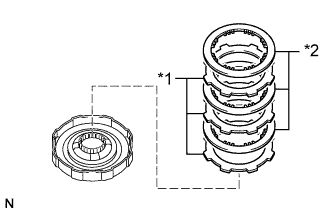
Text in Illustration *1 Pressure Plate *2 No. 3 Brake Disc *3 Plate Install the pressure plate with the flat surface facing the front of the transmission case.
-
Install the 5 No. 3 brake discs and 4 plates.
Install in order *1 - *2 - *3 - *2 - *3 - *2 - *3 - *2 - *3 - *2
-
-
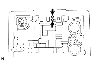
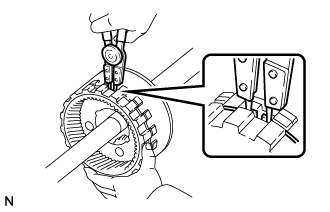
INSPECT PACK CLEARANCE OF NO. 3 BRAKE
-
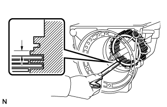
Using a vernier caliper, measure the clearance between the No. 3 brake disc and transmission case as shown in the illustration.
Standard pack clearance 0.52 to 1.27 mm (0.0205 to 0.0499 in.) Tech Tips
-
If the result is not as specified, replace the pressure plate with one of a different thickness.
-
There are 6 types of pressure plates that can be used to adjust the pack clearance. Select the one with the most appropriate thickness.
Pressure Plate Thickness Part No. Mark Thickness 35639-22010 - 2.95 to 3.05 mm (0.117 to 0.120 in.) 35639-22020 325 3.20 to 3.30 mm (0.126 to 0.129 in.) 35639-22030 350 3.45 to 3.55 mm (0.136 to 0.139 in.) 35639-22040 375 3.70 to 3.80 mm (0.146 to 0.149 in.) 35639-22050 400 3.95 to 4.05 mm (0.156 to 0.159 in.) 35639-22060 425 4.20 to 4.30 mm (0.166 to 0.169 in.) -
-
-
INSTALL NO. 2 ONE-WAY CLUTCH
-
Coat the thrust washer with MP grease and install the thrust washer to the front planetary gear sub-assembly.
Note
Make sure that the tabs of the thrust washer are aligned with the cutout portions on the front planetary gear sub-assembly.
-
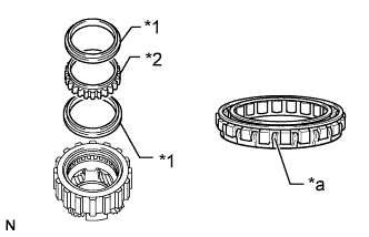
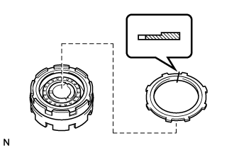
Text in Illustration *1 One-way Clutch Retainer *2 No. 2 One-way Clutch *a Open End Install the No. 2 one-way clutch and 2 retainers to the front planetary gear sub-assembly as shown in the illustration.
Tech Tips
Make sure that the open end of the No. 2 one-way clutch is facing upward.
-
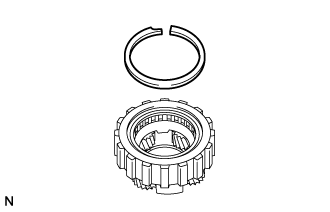
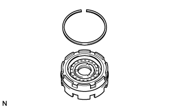
Using a screwdriver, install the snap ring.
Note
-
Be careful not to damage the No. 2 one-way clutch and front planetary gear sub-assembly.
-
Make sure that the snap ring is inserted into the groove.
Tech Tips
Tape the screwdriver tip before use.
-
-
-
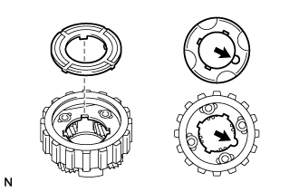
INSPECT NO. 2 ONE-WAY CLUTCH
-
Hold the No. 2 one-way clutch inner race sub-assembly and turn the front planetary gear sub-assembly. Check that the front planetary gear sub-assembly can be turned counterclockwise but cannot be turned clockwise.
Text in Illustration 
Lock 
Free
-
-
INSTALL FRONT PLANETARY GEAR ASSEMBLY
-
Coat the thrust washer with MP grease and install the thrust washer to the front planetary gear sub-assembly.
Note
Make sure that the tabs of the thrust washer are aligned with the holes on the front planetary gear sub-assembly.
-
Install the front planetary gear sub-assembly.
Tech Tips
Mesh the splines of the front planetary gear sub-assembly with the teeth of the No. 3 brake disc set by rotating and pushing the front planetary gear sub-assembly.
-
Position the notched tooth of the No. 2 one-way clutch inner race sub-assembly toward the transmission valve body assembly side of the transmission case and push the No. 2 one-way clutch inner race sub-assembly into place.
Tech Tips
The No. 2 one-way clutch inner race sub-assembly is correctly installed if the snap ring groove is fully visible.
-
Using a screwdriver, install the snap ring.
Note
-
Be careful not to damage the transmission case.
-
Make sure that the snap ring is inserted into the groove.
Tech Tips
Tape the screwdriver tip before use.
-
-
-
INSTALL NO. 1 ONE-WAY CLUTCH ASSEMBLY
-
Coat 2 new oil seal rings with ATF.
-
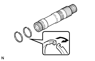
Connect the ends of the oil seal rings and install the oil seal rings to the planetary sun gear sub-assembly.
Note
Do not expand the oil seal rings excessively.
Tech Tips
After installing the oil seal rings, check that they rotate smoothly.
-
Text in Illustration *1 One-way Clutch Retainer *2 No. 1 One-way Clutch *a Open End Install the No. 1 one-way clutch to the outer race with the open end of the No. 1 one-way clutch facing rearward.
-
Install the 2 one-way clutch retainers.
-
Install 2 new retainers to the outer race.
-
Using a pin punch and hammer, stake the claws of the 2 retainers.
-
Install the No. 1 one-way clutch to the planetary sun gear sub-assembly.
-
-
INSPECT NO. 1 ONE-WAY CLUTCH ASSEMBLY
-
Hold the No. 1 one-way clutch and turn the planetary sun gear sub-assembly. Check that the planetary sun gear sub-assembly can be turned counterclockwise but cannot be turned clockwise.
Text in Illustration Lock Free
-
-
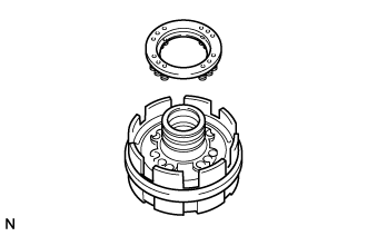
INSTALL NO. 2 BRAKE PISTON
-
Coat a new O-ring with ATF and install it to the center support sub-assembly.
-
Coat a new O-ring with ATF and install it to the brake piston.
-
Install the No. 2 brake piston.
-
Place SST on the No. 2 brake piston.
- SST
- 09350-20015 ( 09369-20040 )
-
Press the No. 2 brake piston into the center support sub-assembly by hand.
Note
Be careful not to damage the O-rings.
-
-
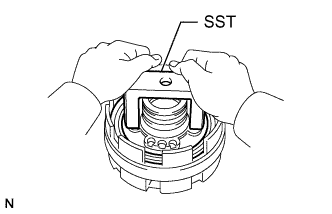
INSTALL NO. 2 BRAKE PISTON RETURN SPRING SUB-ASSEMBLY
-
Place the No. 2 brake piston return spring sub-assembly onto the No. 2 brake piston.
-
Text in Illustration *a Claw Place SST on the No. 2 brake piston return spring sub-assembly and compress the No. 2 brake piston return spring sub-assembly with press.
- SST
- 09350-20015 ( 09369-20040 )
-
Using SST, install the snap ring.
- SST
- 09350-30020 ( 09350-07070 )
Note
-
Make sure the end gap of the snap ring is not aligned with the spring seat claw.
-
Do not expand the snap ring ends excessively.
-
Make sure that the snap ring is inserted into the groove.
-
-
INSTALL NO. 2 BRAKE DISC SET
-
Text in Illustration *1 Plate *2 No. 2 Brake Disc Install the 3 plates and 3 No. 2 brake discs to the center support sub-assembly.
Install in order *1 - *2 - *1 - *2 - *1 - *2 -
Install the flange with the flat end facing downward.
-
Using a screwdriver, install the snap ring.
Note
-
Be careful not to damage the center support sub-assembly.
-
Make sure the end gap of the snap ring is not aligned with the cutout portion of the center support sub-assembly.
-
Make sure that the snap ring is inserted into the groove.
Tech Tips
Tape the screwdriver tip before use.
-
-
-
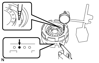
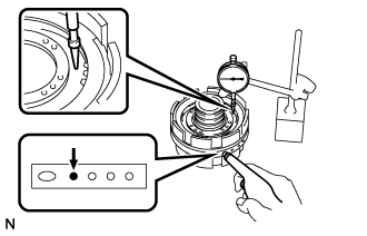
INSPECT PISTON STROKE OF NO. 2 BRAKE PISTON
-
Using a dial indicator, measure the No. 2 brake piston stroke by applying and releasing compressed air (392 kPa (4.0 kgf/cm2, 57 psi)) as shown in the illustration.
Standard piston stroke 0.98 to 1.71 mm (0.0386 to 0.0673 in.) If the stroke is not as specified, inspect the No. 2 brake discs.
-
-
INSTALL NO. 1 BRAKE PISTON
-
Coat 2 new O-rings with ATF and install them to the No. 1 brake piston.
-
Install the No. 1 brake piston to the center support sub-assembly.
-
Place SST on the No. 1 brake piston.
- SST
- 09350-20015 ( 09369-20040 )
-
Press the No. 1 brake piston into the center support sub-assembly by hand.
Note
Be careful not to damage the O-rings.
-
-
INSTALL NO. 1 BRAKE PISTON RETURN SPRING SUB-ASSEMBLY
-
Place the No. 1 brake piston return spring sub-assembly onto the No. 1 brake piston.
-
Text in Illustration *a Claw Place SST on the No. 1 brake piston return spring sub-assembly and compress the No. 1 brake piston return spring sub-assembly with a press.
- SST
- 09350-20015 ( 09369-20040 )
-
Using SST, install the snap ring.
- SST
- 09350-30020 ( 09350-07070 )
Note
-
Make sure the end gap of the snap ring is not aligned with the spring seat claw.
-
Do not expand the snap ring ends excessively.
-
Make sure that the snap ring is inserted into the groove.
-
-
INSTALL NO. 1 BRAKE DISC SET
-
Text in Illustration *1 Plate *2 No. 1 Brake Disc Install the 3 plates and 2 No. 1 brake discs to the center support sub-assembly.
Install in order *1 - *2 - *1 - *1 - *2 -
Install the flange with the rounded edge facing upward.
-
Using a screwdriver, install the snap ring.
Note
-
Be careful not to damage the center support sub-assembly.
-
Make sure the end gap of the snap ring is not aligned with the cutout portion of the center support sub-assembly.
-
Make sure that the snap ring is inserted into the groove.
Tech Tips
Tape the screwdriver tip before use.
-
-
-
INSPECT PISTON STROKE OF NO. 1 BRAKE PISTON
-
Using a dial indicator, measure the No. 1 brake piston stroke by applying and releasing compressed air (392 kPa (4.0 kgf/cm2, 57 psi)) as shown in the illustration.
Standard piston stroke 0.75 to 1.35 mm (0.0296 to 0.0531 in.) If the stroke is not as specified, inspect the No. 1 brake discs.
-
-
INSTALL PLANETARY SUN GEAR SUB-ASSEMBLY WITH NO. 1 ONE-WAY CLUTCH
-
While turning the No. 1 one-way clutch, install the planetary sun gear sub-assembly with No. 1 one-way clutch.
-
Using SST, install the snap ring.
- SST
- 09350-30020 ( 09350-07070 )
Note
-
Do not expand the snap ring ends excessively.
-
Make sure that the snap ring is inserted into the groove.
-
-
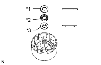
INSTALL REAR CLUTCH PISTON
-
Text in Illustration *1 O-ring *2 Rear No. 2 Clutch Piston *3 Rear Clutch Piston Coat 4 new O-rings with ATF and install them to the rear clutch piston and rear No. 2 clutch piston.
-
Install the rear clutch piston to the rear clutch drum.
-
Install the rear No. 2 clutch piston to the rear clutch drum.
-
Place SST on the rear No. 2 clutch piston.
- SST
- 09350-20015 ( 09369-20040 )
-
Press the rear No. 2 clutch piston into the rear clutch drum by hand.
Note
Be careful not to damage the O-rings.
-
-
INSTALL REAR CLUTCH RETURN SPRING SUB-ASSEMBLY
-
Place the rear clutch return spring sub-assembly onto the rear clutch piston.
-
Text in Illustration *a Claw Place SST on the rear clutch return spring sub-assembly and compress the rear clutch return spring sub-assembly with a press.
- SST
- 09350-20015 ( 09369-20040 )
- 09350-30020 ( 09350-07070 )
-
Install the snap ring with a snap ring expander.
Note
-
Make sure the end gap of the snap ring is not aligned with the spring seat claw.
-
Do not expand the snap ring ends excessively.
-
Make sure that the snap ring is inserted into the groove.
-
-
-
INSTALL REAR CLUTCH DISC SET
-
Text in Illustration *1 Plate *2 Rear Clutch Disc Install the 3 plates and 3 rear clutch discs.
Install in order *1 - *2 - *1 - *2 - *1 - *2 -
Install the flange with the flat side facing downward.
-
Using a screwdriver, install the snap ring.
Note
-
Be careful not to damage the rear clutch drum.
-
Make sure the end gap of the snap ring is not aligned with the cutout portion of the rear clutch drum.
-
Make sure that the snap ring is inserted into the groove.
Tech Tips
Tape the screwdriver tip before use.
-
-
-
INSPECT PISTON STROKE OF REAR CLUTCH PISTON
-
Place the rear clutch drum onto the center support sub-assembly.
-
Using a dial indicator, measure the rear clutch piston stroke by applying and releasing compressed air (392 kPa (4.0 kgf/cm2, 57 psi)) as shown in the illustration.
Standard piston stroke 0.90 to 1.30 mm (0.0355 to 0.0511 in.) If the piston stroke is not as specified, parts may have been assembled incorrectly. Check the parts and reassemble again.
Tech Tips
-
If the piston stroke is still not as specified, replace the flange with one of a different thickness.
-
There are 3 types of flanges that can be used to adjust the pack clearance. Select the one with the most appropriate thickness.
Flange Thickness Part No. Mark Thickness 35675-22120 A 3.475 to 3.600 mm (0.137 to 0.141 in.) 35675-22130 B 3.675 to 3.800 mm (0.145 to 0.149 in.) 35675-22140 - 3.925 to 4.050 mm (0.155 to 0.159 in.)
-
-
-
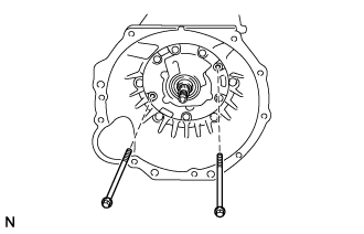
INSTALL CENTER SUPPORT SUB-ASSEMBLY
-
Coat 3 new oil seal rings with ATF.
-
Connect the ends of the oil seal rings and install the oil seal rings to the center support sub-assembly.
Note
Do not expand the oil seal rings excessively.
Tech Tips
After installing the oil seal rings, check that they rotate smoothly.
-
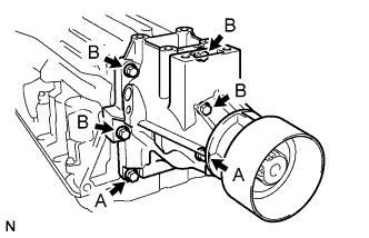
Position the center support sub-assembly so that the bolt holes and oil holes are facing the transmission valve body assembly and are aligned with the bolt holes and oil holes of the transmission case, and then install the center support sub-assembly.
-
Install the 2 washers to the 2 bolts.
-
Temporarily install the 2 bolts together with the washers.
-
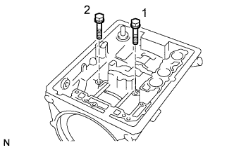
Tighten the 2 bolts in the order shown in the illustration.
- Torque:
- 25 N*m { 260 kgf*cm, 19 ft.*lbf }
-
-
INSTALL REAR CLUTCH DRUM
-
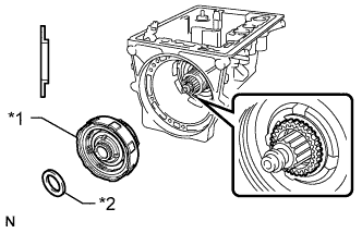
Text in Illustration *1 Rear Clutch Drum *2 Rear Race F Install the rear clutch drum.
Tech Tips
-
Mesh the splines of the rear clutch drum with the teeth of the No. 1 brake discs by rotating and pushing the rear clutch drum.
-
If the rear clutch drum is fully meshed with the No. 1 brake discs, the center of the rear clutch drum splines will be flush with the end of the planetary sun gear sub-assembly.
-
-
Coat the race with MP grease and install it to the rear clutch drum.
Race Diameter Item Inside Outside Rear Race F 27.58 mm (1.09 in.) 44.70 mm (1.76 in.) Note
Make sure the race is installed so that it is oriented correctly.
-
-
INSTALL FRONT CLUTCH PISTON
-
Coat 2 new O-rings with ATF and install them to the front clutch piston.
-
Place the front clutch drum onto the overdrive case sub-assembly.
-
Install the front clutch piston to the front clutch drum.
-
Place SST on the front clutch piston.
- SST
- 09350-20015 ( 09369-20040 )
-
Press the front clutch piston into the front clutch drum by hand.
Note
Be careful not to damage the O-rings.
-
-
INSTALL FRONT CLUTCH RETURN SPRING SUB-ASSEMBLY
-
Place the front clutch return spring sub-assembly onto the front clutch piston.
-
Text in Illustration *a Claw Place SST on the front clutch return spring sub-assembly and compress the front clutch return spring sub-assembly with a press.
- SST
- 09350-20015 ( 09369-20040 )
- 09350-30020 ( 09350-07070 )
-
Using a snap ring expander, install the snap ring.
Note
-
Make sure the end gap of the snap ring is not aligned with the spring seat claw.
-
Do not expand the snap ring ends excessively.
-
Make sure that the snap ring is inserted into the groove.
-
-
-
INSTALL FRONT CLUTCH DISC SET
-
Text in Illustration *1 Plate *2 Front Clutch Disc Install the 4 plates and 3 front clutch discs.
Install in order *1 - *2 - *1 - *2 - *1 - *2 - *1 -
Text in Illustration *1 Front Clutch Disc *2 Snap Ring Install the snap ring.
Note
-
Make sure the end gap of the snap ring is not aligned with the cutout portion of the front clutch drum.
-
Be careful not to damage the front clutch drum.
-
Make sure that the snap ring is inserted into the groove.
Tech Tips
Protective tape the screwdriver tip before use.
-
-
Install the front clutch disc.
-
-
INSPECT PISTON STROKE OF FRONT CLUTCH PISTON
-
In order to check the piston stroke, install the rear clutch hub.
-
Install the snap ring.
-
Using SST and a dial indicator, measure the front clutch piston sub-assembly stroke by applying and releasing compressed air (392 kPa (4.0 kgf/cm2, 57 psi)) as shown in the illustration.
- SST
- 09350-20015 ( 09350-06120 )
Standard piston stroke 1.40 to 1.60 mm (0.0552 to 0.0629 in.) If the piston stroke is not as specified, parts may have been assembled incorrectly. Check the parts and reassemble again.
Tech Tips
-
If the piston stroke is still not as specified, replace the plates with ones of a different thickness.
-
There are 2 types of plates that can be used to adjust the pack clearance. Select the one with the most appropriate thickness.
Plate Thickness Part No. Thickness 35634-22040 1.75 to 1.85 mm (0.0689 to 0.0728 in.) 34634-30070 1.95 to 2.05 mm (0.0768 to 0.0807 in.)
-
-
INSTALL FRONT CLUTCH HUB AND REAR CLUTCH HUB
-
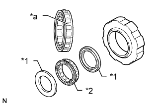
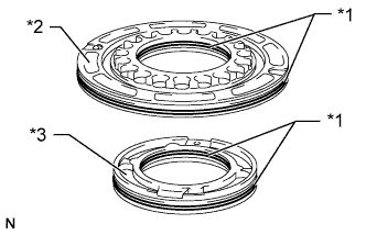
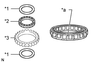
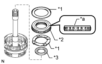
Text in Illustration *1 Rear Race E *2 Bearing E *3 Front Race E Coat the bearing and races with MP grease and install them to the front clutch drum.
Bearing and Race Diameter Item Inside Outside Front Race E 24.05 mm (0.947 in.) 37.59 mm (1.48 in.) Bearing E 23.34 mm (0.919 in.) 37.59 mm (1.48 in.) Rear Race E 21.41 mm (0.843 in.) 37.59 mm (1.48 in.) Note
Make sure the bearing and races are installed so that they are oriented correctly.
-
Install the front clutch hub to the front clutch drum.
Tech Tips
Mesh the splines of the front clutch hub with the teeth of the front clutch disc set by rotating and pushing the front clutch hub.
-
Install the rear clutch hub to the front clutch drum.
-
Install the snap ring.
Note
-
Make sure the end gap of the snap ring is not aligned with the cutout portion of the front clutch drum.
-
Be careful not to damage the front clutch drum.
-
Make sure that the snap ring is inserted into the groove.
Tech Tips
Tape the screwdriver tip before use.
-
-
Remove the front clutch drum from the overdrive case sub-assembly.
-
-
INSTALL FRONT CLUTCH DRUM
-
Text in Illustration *1 Bearing D *2 Race F *3 Bearing F Coat the 2 bearings and race with MP grease and install them to the front clutch drum.
Bearing and Race Diameter Item Inside Outside Bearing D 23.34 mm (0.919 in.) 37.59 mm (1.48 in.) Race F 30.00 mm (1.18 in.) 47.9 mm (1.89 in.) Bearing F 28.30 mm (1.11 in.) 46.48 mm (1.83 in.) Note
Make sure the bearings and race are installed so that they are oriented correctly.
-
Install the front clutch drum to the transmission case.
Tech Tips
Mesh the splines of the front clutch drum with the teeth of the rear clutch disc set by rotating and pushing the front clutch drum.
-
-
INSPECT INSTALLATION DISTANCE OF FRONT CLUTCH DRUM
-
Place SST on the transmission case.
- SST
- 09350-20015 ( 09370-12010 )
-
Using a vernier caliper, measure the distance between the top of the front clutch drum and SST.
If the measured distance is the same as the measured distance noted during disassembly, the front clutch drum is installed correctly.
-
-
INSTALL OVERDRIVE BRAKE PISTON
-
Coat 2 new O-rings with ATF and install them to the overdrive brake piston.
-
Press the overdrive brake piston into the overdrive case sub-assembly by hand to install it.
Note
Be careful not to damage the O-rings.
-
-
INSTALL OVERDRIVE BRAKE RETURN SPRING SUB-ASSEMBLY
-
Install the overdrive brake return spring sub-assembly.
-
Text in Illustration *a Protective Tape Install the snap ring while pushing the overdrive brake return spring sub-assembly with a screwdriver.
Note
-
Make sure the end gap of the snap ring is not aligned with the cutout portion of the overdrive transmission case.
-
Be careful not to damage the automatic transmission extension housing.
-
Make sure that the snap ring is inserted into the groove.
Tech Tips
Tape the screwdriver tip before use.
-
-
-
INSTALL OVERDRIVE PLANETARY RING GEAR SUB-ASSEMBLY
-
Text in Illustration *1 Front Race C *2 Bearing C *3 Rear Race C Coat the bearing and races with MP grease and install them to the overdrive case sub-assembly.
Bearing and Race Diameter Item Inside Outside Front Race C 30.00 mm (1.18 in.) 48.54 mm (1.91 in.) Bearing C 28.30 mm (1.11 in.) 46.48 mm (1.83 in.) Rear Race C 27.58 mm (1.09 in.) 44.70 mm (1.76 in.) Note
Make sure the bearing and races are installed so that they are oriented correctly.
-
Install the overdrive planetary ring gear.
-
-
INSTALL OVERDRIVE BRAKE DISC SET
-
Text in Illustration *1 Plate *2 Overdrive Brake Disc *3 Flange Install the 3 plates, 3 overdrive brake discs and flange with the rounded edge of the flange facing upward.
Install in order *1 - *2 - *1 - *2 - *1 - *2 - *3 -
Using a screwdriver, install the snap ring.
Note
-
Make sure the end gap of the snap ring is not aligned with the cutout portion of the overdrive case sub-assembly.
-
Be careful not to damage the overdrive case sub-assembly.
-
Make sure that the snap ring is inserted into the groove.
Tech Tips
Tape the screwdriver tip before use.
-
-
-
INSTALL OVERDRIVE BRAKE ASSEMBLY
-
Temporarily install SST to the transmission case.
- SST
- 09350-20015 ( 09362-30011 )
Tech Tips
Remove SST after installation of the oil pump assembly.
-
Text in Illustration *1 Thrust Washer *2 Race D Coat the thrust washer and race with MP grease and install them to the overdrive case sub-assembly.
Race Diameter Item Inside Outside Race D 24.05 mm (0.947 in.) 37.59 mm (1.48 in.) Note
Make sure the race is installed so that it is oriented correctly.
-
Coat 2 new oil seal rings with ATF.
-
Connect the ends of the oil seal rings and install the oil seal rings to the overdrive case sub-assembly.
Note
Do not expand the rings excessively.
Tech Tips
After installing the oil seal rings, check that they rotate smoothly.
-
Slide the overdrive case sub-assembly onto the 2 guide bolts (SST) with the cutout portion of the overdrive case sub-assembly facing the transmission valve body assembly to install the overdrive case sub-assembly.
-
-
INSPECT PACK CLEARANCE OF OVERDRIVE BRAKE PISTON
-
Place the overdrive case sub-assembly onto the transmission case with the cutout of the overdrive case sub-assembly facing downward.
Tech Tips
Make sure that the oil hole of the overdrive case sub-assembly is aligned with the oil hole of the transmission case.
-
Using a dial indicator, measure the overdrive brake disc set pack clearance by applying and releasing compressed air (392 kPa (4.0 kgf/cm2, 57 psi)) as shown in the illustration.
Standard pack clearance 0.75 to 1.25 mm (0.0296 to 0.0492 in.) If the piston stroke is not as specified, parts may have been assembled incorrectly. Check the parts and reassemble again.
Tech Tips
-
If the piston stroke is still not as specified, replace the plates with ones of a different thickness.
-
There are 2 types of plates that can be used to adjust the pack clearance. Select the one with the most appropriate thickness.
Plate Thickness Part No. Thickness 35634-30080 1.95 to 2.05 mm (0.0768 to 0.0807 in.) 34634-30010 2.25 to 2.35 mm (0.0886 to 0.0925 in.) -
-
Remove the overdrive case sub-assembly from the transmission case.
-
-
INSTALL OVERDRIVE ONE-WAY CLUTCH
-
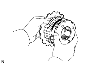
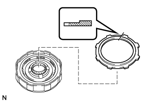
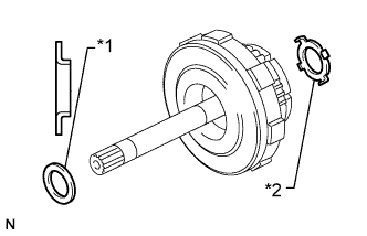
Text in Illustration *1 One-way Clutch Retainer *2 Overdrive One-way Clutch *3 Outer Race *a Open End Install the overdrive one-way clutch to the outer race with the open end of the overdrive one-way clutch facing upward.
-
Install the 2 one-way clutch retainers.
-
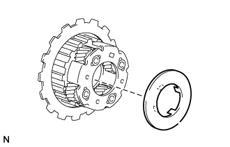
Text in Illustration *1 Thrust Washer *2 Overdrive One-way Clutch *3 Bearing *a Open End Coat the bearing with MP grease and install it to the overdrive planetary gear assembly.
Bearing Diameter Item Inside Outside Bearing B 37.3 mm (1.47 in.) 52.52 mm (2.07 in.) Note
Make sure the bearing and thrust washers are installed so that they are oriented correctly.
-
Install the 2 washers and overdrive one-way clutch to the overdrive planetary gear assembly.
-
Text in Illustration *a Protective Tape Using a screwdriver, install the snap ring.
Note
-
Be careful not to damage the overdrive planetary gear assembly.
-
Make sure that the snap ring is inserted into the groove.
Tech Tips
Tape the screwdriver tip before use.
-
-
-
INSTALL OVERDRIVE DIRECT CLUTCH PISTON
-
Coat 2 new O-rings with ATF and install them to the overdrive direct clutch piston.
-
Install the overdrive direct clutch piston.
-
Place SST on the overdrive direct clutch piston.
- SST
- 09350-20015 ( 09369-20040 )
-
Press the overdrive direct clutch piston into the overdrive direct clutch drum by hand.
Note
Be careful not to damage the O-rings.
-
-
INSTALL OVERDRIVE CLUTCH RETURN SPRING SUB-ASSEMBLY
-
Install the overdrive clutch return spring sub-assembly to the overdrive direct clutch drum.
-
Text in Illustration *a Claw Place SST on the overdrive clutch return spring sub-assembly and compress the overdrive clutch return spring sub-assembly with a press.
- SST
- 09350-20015 ( 09369-20040 )
-
Using SST, install the snap ring.
- SST
- 09350-30020 ( 09350-07070 )
Note
-
Make sure the end gap of the snap ring is not aligned with the spring seat claw.
-
Do not expand the snap ring ends excessively.
-
Make sure that the snap ring is inserted into the groove.
-
-
INSTALL OVERDRIVE CLUTCH DISC SET
-
Text in Illustration *1 Cushion Plate *2 Flange Install the cushion plate and flange with the rounded edge facing upward.
Install in order *1 - *2 -
Using a screwdriver, install the snap ring.
Note
-
Make sure the end gap of the snap ring is not aligned with the cutout portion of the overdrive direct clutch drum.
-
Be careful not to damage the overdrive direct clutch drum.
-
Make sure that the snap ring is inserted into the groove.
Tech Tips
Tape the screwdriver tip before use.
-
-
Install the overdrive clutch disc.
-
-
INSTALL OVERDRIVE BRAKE HUB
-
Install the overdrive brake hub to the overdrive direct clutch drum.
-
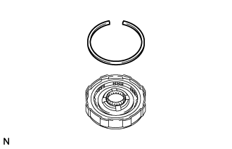
Using a screwdriver, install the snap ring.
Note
-
Make sure the end gap of the snap ring is not aligned with the cutout portion of the overdrive direct clutch drum.
-
Be careful not to damage the overdrive direct clutch drum.
-
Make sure that the snap ring is inserted into the groove.
Tech Tips
Tape the screwdriver tip before use.
-
-
-
INSPECT PISTON STROKE OF OVERDRIVE DIRECT CLUTCH PISTON
-
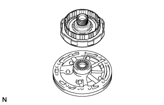
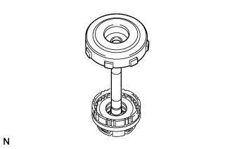
Place the overdrive direct clutch drum sub-assembly onto the oil pump assembly.
-
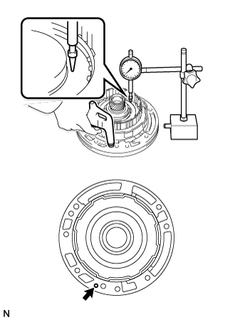
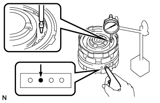
Using a dial indicator, measure the overdrive direct clutch piston sub-assembly stroke by applying and releasing compressed air (392 kPa (4.0 kgf/cm2, 57 psi)) as shown in the illustration.
Standard piston stroke 1.74 to 2.44 mm (0.0686 to 0.0960 in.) If the result is not as specified, inspect the overdrive clutch disc set.
-
Remove the overdrive direct clutch drum sub-assembly from the oil pump assembly.
-
-
INSTALL OVERDRIVE DIRECT CLUTCH DRUM
-
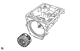
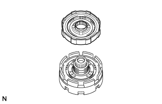
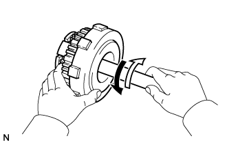
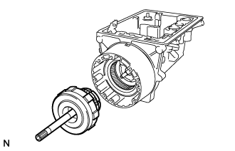
Install the overdrive direct clutch drum to the overdrive planetary gear assembly.
Tech Tips
Mesh the splines of the overdrive planetary gear assembly with the teeth of the overdrive clutch disc set by rotating and pushing the overdrive planetary gear assembly.
-
-
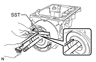
INSPECT OVERDRIVE ONE-WAY CLUTCH
-
Hold the overdrive direct clutch drum sub-assembly and turn the overdrive planetary gear assembly. Check that the overdrive planetary gear assembly can be turned clockwise but cannot be turned counterclockwise.
Text in Illustration Lock Free
-
-
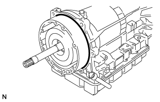
INSTALL OVERDRIVE PLANETARY GEAR ASSEMBLY WITH OVERDRIVE DIRECT CLUTCH DRUM
-
Text in Illustration *1 Race A *2 Thrust Washer Coat the thrust washer and race with MP grease and install them to the overdrive planetary gear assembly with overdrive direct clutch drum.
Race Diameter Item Inside Outside Race A 24.32 mm (0.957 in.) 39.2 mm (1.54 in.) Note
Make sure the race is installed so that it is oriented correctly.
-
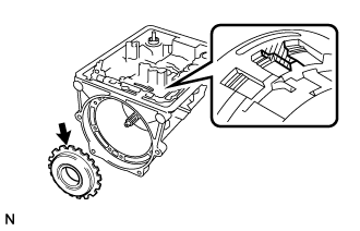
Install the overdrive planetary gear assembly with overdrive direct clutch assembly to the transmission case.
Tech Tips
Mesh the splines of the overdrive planetary gear assembly with the teeth of the overdrive brake disc set by rotating and pushing the overdrive planetary gear assembly.
-
-
INSPECT INSTALLATION DISTANCE OF OVERDRIVE DIRECT CLUTCH DRUM
-
Place SST on the transmission case.
- SST
- 09350-20015 ( 09370-12010 )
-
Using a vernier caliper, measure the distance between the top of the overdrive direct clutch drum and SST.
If the measured distance is the same as the measured distance noted during disassembly, the overdrive direct clutch drum is installed correctly.
-
-
INSTALL AUTOMATIC TRANSMISSION HOUSING
-
Coat a new O-ring with ATF and install it to the overdrive case sub-assembly.
-
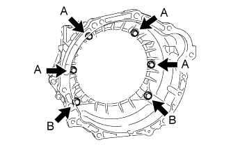
Temporarily install the transmission housing with the 6 bolts.
-
Tighten the bolts.
- Torque:
- for Bolt A
- 34 N*m { 345 kgf*cm, 25 ft.*lbf }
- for Bolt B
- 57 N*m { 579 kgf*cm, 42 ft.*lbf }
-
-
INSTALL OIL PUMP ASSEMBLY
-
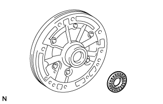
Coat the bearing with MP grease and install it to the oil pump assembly.
Bearing Diameter Item Inside Outside Bearing A 24.32 mm (0.957 in.) 43.2 mm (1.70 in.) Note
Make sure the race is installed so that it is oriented correctly.
-
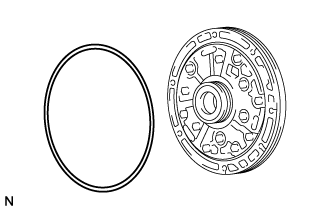
Coat a new O-ring with ATF and install it to the oil pump assembly.
-
Slide the oil pump assembly onto SST (2 guide bolts) to install it.
- SST
- 09350-20015 ( 09370-12010 )
-
Clean the 7 bolts.
-
Apply adhesive to the bolt heads.
Adhesive Toyota Genuine Adhesive 1344, Three Bond 1344 or equivalent -
Temporarily install the 5 bolts.
-
Using a screwdriver, remove SST.
-
Temporarily install the 2 bolts.
-
Tighten the 7 bolts.
- Torque:
- 21 N*m { 215 kgf*cm, 16 ft.*lbf }
-
-
INSPECT INPUT SHAFT ROTATION
-
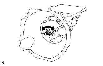
Check that the input shaft rotates smoothly.
-
-
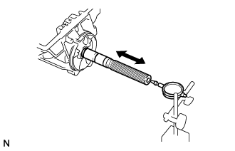
INSPECT OUTPUT SHAFT
-
Using a dial indicator, measure the end play of the output shaft assembly while moving the output shaft assembly by hand.
Standard end play 0.3 to 0.9 mm (0.0119 to 0.0354 in.) If the end play is not as specified, check for improper installation.
-
Check that the output shaft assembly rotates smoothly.
-
-
INSPECT INDIVIDUAL PISTON OPERATION
-
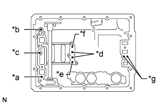
Text in Illustration *a Overdrive Direct Clutch Oil Hole *b Overdrive Brake Oil Hole *c Rear Clutch Oil Hole *d Front Clutch Oil Hole *e No. 1 Brake Oil Hole *f No. 2 Brake Oil Hole *g No. 3 Brake Oil Hole Check for operating noise while applying compressed air to the oil holes indicated in the illustration.
If there is no noise, disassemble the parts and check the installation condition of the parts.
-
-
INSTALL PARKING LOCK PAWL SHAFT
-
Text in Illustration *1 Parking Lock Pawl Shaft *2 E-ring *3 Parking Lock Pawl *4 Spring Install a new E-ring to the parking lock pawl shaft.
-
Install the parking lock pawl, parking lock pawl shaft and spring.
-
-
INSTALL PARKING LOCK ROD SUB-ASSEMBLY
-
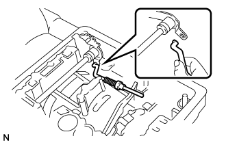
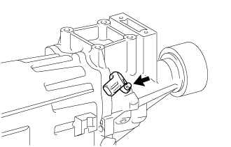
Connect the parking lock rod sub-assembly to the manual valve lever to install it.
-
-
INSTALL PARKING LOCK PAWL BRACKET
-
Install the parking lock pawl bracket with the 2 washers and 2 bolts.
- Torque:
- 7.4 N*m { 75 kgf*cm, 65 in.*lbf }
-
Shift the manual valve lever to the P position, and then confirm that the front planetary ring gear is correctly locked by the parking lock pawl.
-
-
INSTALL ACCUMULATOR PISTON AND SPRING
-
Coat 6 new O-rings with ATF and install them to each accumulator piston.
-
Text in Illustration *1 C - 1 Accumulator Piston *2 C - 2 Accumulator Piston *3 B - 2 Accumulator Piston Install the 3 springs and 3 accumulator pistons to the 3 holes as shown in the illustration.
Piston Diameter Piston Outer Diameter C - 1 31.85 mm (1.25 in.) C - 2 31.85 mm (1.25 in.) B - 2 34.8 mm (1.37 in.) Spring Diameter Spring Free Length
Outer Diameter
Color C - 1 75.03 mm (2.95 in.)
17.00 mm (0.669 in.)
White or Blue C - 2 62.27 mm (2.45 in.)
16.4 mm (0.646 in.)
White or Purple B - 2 56.40 mm (2.22 in.)
18.79 mm (0.740 in.)
Green
-
-
INSTALL TRANSMISSION VALVE BODY ASSEMBLY
-
Align the groove of the manual valve with the pin of the manual valve lever.
-
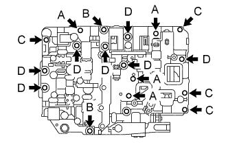
Install the valve body with the 17 bolts.
- Torque:
- 9.8 N*m { 100 kgf*cm, 87 in.*lbf }
Tech Tips
Each bolt length is indicated below.
Bolt A: 28 mm (1.10 in.)
Bolt B: 30 mm (1.18 in.)
Bolt C: 36 mm (1.42 in.)
Bolt D: 45 mm (1.77 in.)
-
-
INSTALL TRANSMISSION WIRE
-
Coat a new O-ring with ATF, and install it to the transmission wire.
-
Install the transmission wire to the transmission case with the bolt.
- Torque:
- 16 N*m { 160 kgf*cm, 12 ft.*lbf }
-
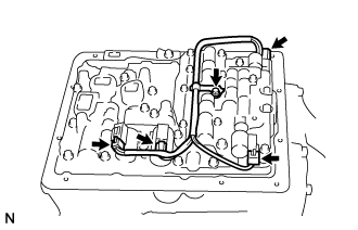
Connect the 4 connectors to the 4 shift solenoid valves.
-
Install the clamp with the bolt to the transmission valve body assembly.
- Torque:
- 9.8 N*m { 100 kgf*cm, 87 in.*lbf }
-
-
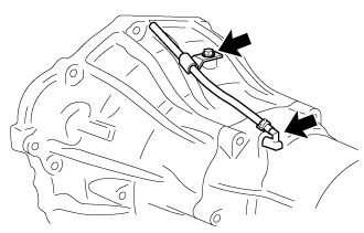
INSTALL OVERDRIVE BRAKE TUBE
-
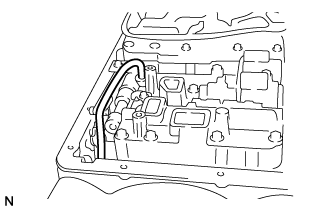
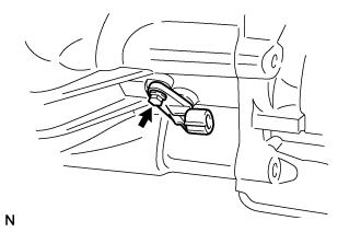
Using a plastic-faced hammer, tap in the overdrive brake tube as shown in the illustration.
Note
Be careful not to bend or damage the tube.
-
-
INSTALL VALVE BODY OIL STRAINER ASSEMBLY
-
Install 3 new gaskets to the valve body oil strainer assembly.
-
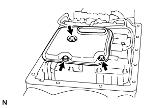
Install the valve body oil strainer assembly with the 3 bolts.
- Torque:
- 5.4 N*m { 55 kgf*cm, 48 in.*lbf }
-
-
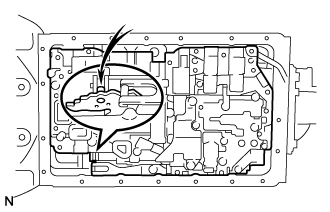
INSTALL AUTOMATIC TRANSMISSION OIL PAN SUB-ASSEMBLY
-
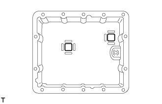
Install the 2 transmission oil cleaner magnets to the locations indicated in the illustration.
Note
Be careful not to spill oil on the contacting surfaces of the transmission case and automatic transmission oil pan sub-assembly.
-
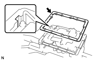
Install a new automatic transmission oil pan gasket to the transmission case.
Tech Tips
Align the cutout part of the automatic transmission oil pan gasket with the transmission case.
-
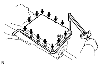
Install the automatic transmission oil pan sub-assembly with the 14 bolts.
- Torque:
- 4.4 N*m { 45 kgf*cm, 39 in.*lbf }
-
-
INSTALL TRANSMISSION CASE REAR COVER
-
Text in Illustration *1 Gasket *2 Transmission Case Rear Cover Install a new gasket and the transmission case rear cover with the 3 screws.
-
-
INSTALL SENSOR ROTOR
-
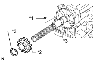
Text in Illustration *1 Key *2 Sensor Rotor *3 Snap Ring Using a snap ring expander, install the front side snap ring.
Note
-
Do not expand the snap ring ends excessively.
-
Make sure that the snap ring is inserted into the groove.
-
-
Install the key and sensor rotor.
-
Using a snap ring expander, install the rear side snap ring.
Note
-
Do not expand the snap ring ends excessively.
-
Make sure that the snap ring is inserted into the groove.
-
-
-
INSTALL EXTENSION HOUSING DUST DEFLECTOR
-
Using a screwdriver and hammer, tap in a new extension housing dust deflector.
-
-
INSTALL AUTOMATIC TRANSMISSION EXTENSION HOUSING OIL SEAL
-
Coat the lip of a new extension housing rear oil seal with MP grease.
-
Using SST and a hammer, tap in the oil seal.
- SST
- 09309-37010
Standard depth 6.2 to 6.8 mm (0.245 to 0.267 in.) Note
Be careful not to damage the lip of the extension housing rear oil seal.
-
Install a new dust seal to a new retainer.
-
Using SST and a hammer, tap in the dust seal together with the retainer.
- SST
- 09309-37010
Standard distance 0.7 to 1.3 mm (0.0276 to 0.0511 in.)
-
-
INSTALL EXTENSION HOUSING BUSH APPLY TUBE
-
Text in Illustration *1 Extension Housing Bush Apply Tube *2 Bush Apply Tube Gasket Install the extension housing bush apply tube and a new bush apply tube gasket to the extension housing sub-assembly.
-
-
INSTALL EXTENSION HOUSING SUB-ASSEMBLY
-
Clean and degrease the threads of the 6 bolts and the contact surfaces of the transmission case and the extension housing sub-assembly with non-residue solvent.
-
Install a new gasket and the extension housing to the case.
-
Apply adhesive to 2 or 3 threads on the end of the 6 bolts.
Adhesive Toyota Genuine Adhesive 1344, Three Bond 1344 or equivalent -
Install the extension housing sub-assembly to the transmission case with the 6 bolts.
- Torque:
- 36 N*m { 370 kgf*cm, 27 ft.*lbf }
Tech Tips
Each bolt length is indicated below.
for Bolt A: 35 mm (1.38 in.)
for Bolt B: 45 mm (1.77 in.)
-
-
INSTALL SPEED SENSOR
-
Coat a new O-ring with ATF and install it to the speed sensor SP2.
-
Install the speed sensor SP2 with the bolt.
- Torque:
- 5.4 N*m { 55 kgf*cm, 48 in.*lbf }
-
Coat a new O-ring with ATF and install it to the speed sensor NC0.
-
Clean the bolt and the bolt hole.
-
Apply adhesive to 2 or 3 threads on the end of the bolt.
Adhesive Toyota Genuine Adhesive 1344, Three Bond 1344 or equivalent -
Install the speed sensor NC0 with the bolt.
- Torque:
- 5.4 N*m { 55 kgf*cm, 48 in.*lbf }
-
-
INSTALL OIL COOLER TUBE UNION
-
Coat 2 new O-rings with ATF and install one to each oil cooler tube union.
-
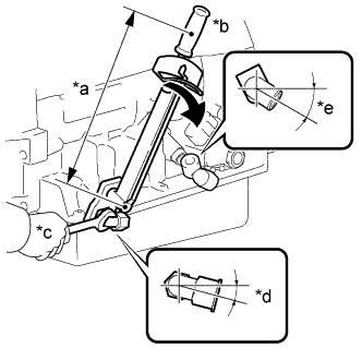
Text in Illustration *a Fulcrum Length *b Turn *c Hold *d -13 to -17° *e -28 to -32° Using SST, install the 2 oil cooler tube unions.
- SST
- 09268-78010
- Torque:
- without SST
- 25 N*m { 250 kgf*cm, 18 ft.*lbf }
- with SST
- 21 N*m { 210 kgf*cm, 15 ft.*lbf }
Tech Tips
-
Use a torque wrench with a fulcrum length of 180 mm (7.09 in.). When using a torque wrench with a fulcrum length that is not 180 mm (7.09 in.), calculate the torque specification for the torque wrench and SST based on the "without SST" torque specification.
-
Make sure SST and the wrench are connected in a straight line.
-
-
INSTALL ATF TEMPERATURE SENSOR
-
Coat the O-ring of the ATF temperature sensor with ATF.
-

Install the ATF temperature sensor.
- Torque:
- 15 N*m { 150 kgf*cm, 11 ft.*lbf }
-
-
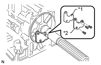
INSTALL PARK/NEUTRAL POSITION SWITCH ASSEMBLY
-
Clean the bolt and the bolt hole.
-
Apply adhesive to 2 or 3 threads on the end of the bolt.
Adhesive Toyota Genuine Adhesive 1344, Three Bond 1344 or equivalent -
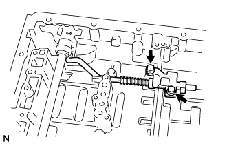
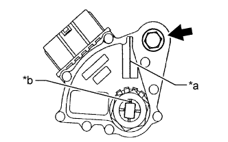
Install the park/neutral position switch assembly to the manual valve lever shaft, and then temporarily install the bolt.
Tech Tips
Tighten the bolt to the specified torque when adjusting the park/neutral position switch assembly.
-
Install a lock washer with the nut.
- Torque:
- 6.9 N*m { 70 kgf*cm, 61 in.*lbf }
-
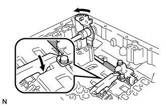
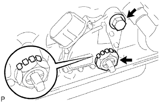
Using the transmission control shaft lever LH, turn the manual valve lever shaft clockwise until it stops, and then turn it counterclockwise 2 notches to set it to the N position.
-
Text in Illustration *a Neutral Basic Line *b Groove Align the neutral basic line with the groove of the park/neutral position switch assembly and tighten the bolt.
- Torque:
- 5.4 N*m { 55 kgf*cm, 48 in.*lbf }
-
Using a screwdriver, bend the tabs of the lock washer.
-
-
INSTALL TRANSMISSION CONTROL SHAFT LEVER LH
-
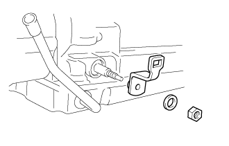
Install the transmission control shaft lever LH with the spring washer and nut.
- Torque:
- 16 N*m { 160 kgf*cm, 12 ft.*lbf }
-
-
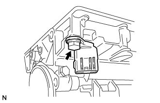
INSTALL BREATHER HOSE SUB-ASSEMBLY
-
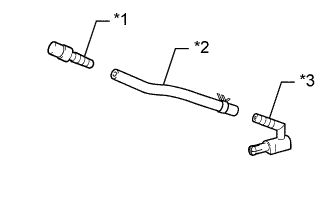
Text in Illustration *1 No. 1 Breather Plug *2 Breather Hose *3 No. 2 Breather Plug Install the No. 1 breather plug and No. 2 breather plug to the breather hose.
-
Install the breather hose sub-assembly to the transmission case.
-
Install the clamp to the automatic transmission housing with the bolt.
- Torque:
- 7.4 N*m { 75 kgf*cm, 65 in.*lbf }
-
-
INSTALL DRAIN PLUG
-
Install a new gasket and the drain plug.
- Torque:
- 20 N*m { 205 kgf*cm, 15 ft.*lbf }
-