- Click here
CONNECT TRANSMISSION CONTROL CABLE ASSEMBLY
-
Rolled up the floor carpet of the front seat LH and connect the transmission control cable assembly with the 2 bolts.
8.0 N*m 82 kgf*cm 71 in.*lbf -
Install the transmission control cable bracket No. 3 to the body with the 2 nuts.
5.5 N*m 56 kgf*cm 49 in.*lbf -
Install the transmission control cable assembly to the transmission control cable bracket No. 3.
-
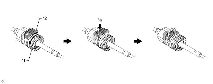
Turn the nut of the transmission control cable assembly approximately 180° counterclockwise. While holding the nut in place, securely push the stopper in all the way.
Table 1. Text in Illustration *1 Stopper *2 Nut *a Push in - - Note:Do not over-rotate the nut as it will come off the internal spring and the transmission control cable assembly will not be reusable.
-
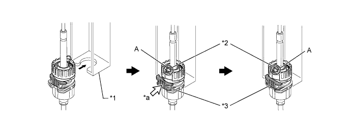
Install the outer part of the transmission control cable assembly to the shift lock control unit assembly. Check that the spring is positioned at "A" and push in the stopper.
Table 2. Text in Illustration *1 Shift Lock Control Unit Assembly *2 Spring *3 Stopper - - *a Push in - - Note:Ensure that the groove on the transmission control cable assembly is securely fitted to the shift lock control unit assembly.
Tip:If the stopper cannot be pushed in, slightly turn the nut clockwise and then push in the stopper again.
-
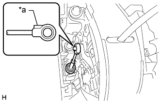
Connect the end of the transmission control cable assembly to the shift lock control unit assembly.
Table 3. Text in Illustration *a Protrusion Note:
-
Securely connect the cable end until if fits securely against the base of the pin.
-
Connect the cable end with the protrusion facing the front of the vehicle.
-
-
- Click here
INSTALL INSTRUMENT PANEL FINISH PANEL LOWER CENTER
-
Введите в зацепление 8 захватов, чтобы установить нижнюю центральную отделочную накладку панели приборов.
-
- Click here
INSTALL PARKING BRAKE HOLE COVER
-
Введите в зацепление 6 захватов, чтобы установить крышку отверстия стояночного тормоза.
-
- Click here
INSTALL INSTRUMENT PANEL FINISH PANEL LOWER
-
Подсоедините трос устройства блокировки топливной крышки и трос управления замком капота к нижней отделочной накладке панели приборов.
-
Установите нижнюю отделочную накладку панели приборов и закрепите ее 4 фиксаторами.
-
Установите 2 фиксатора.
-
- Click here
INSTALL INSTRUMENT PANEL UNDER COVER SUB-ASSEMBLY NO. 1
-
Введите в зацепление 3 захвата, чтобы установить нижнюю крышку панели приборов № 1.
-
Установите 2 фиксатора.
-
- Click here
INSTALL FLOOR SHIFT POSITION INDICATOR HOUSING SUB-ASSEMBLY
-
Attach the 8 claws to install the floor shift position indicator housing sub-assembly.
-
- Click here
INSTALL SHIFT LEVER KNOB
-
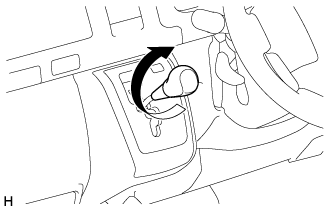
Install the shift lever knob and twist it in the direction indicated by the arrow.
-
- Click here
INSTALL TRANSMISSION CONTROL CABLE ASSEMBLY
-
Install the transmission control cable bracket No. 2 to the under body with the 2 nuts.
5.5 N*m 56 kgf*cm 49 in.*lbf -
Connect the transmission control cable assembly to the transmission control cable bracket No. 2.
-
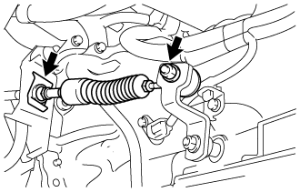
Install the transmission control cable assembly with the 2 bolts.
14 N*m 143 kgf*cm 10 ft.*lbf -
Connect the transmission control cable assembly to the control shaft lever and transmission control cable bracket No. 1 with a clip and the nut.
15 N*m 148 kgf*cm 11 ft.*lbf
-
- Click here
ADJUST SHIFT LEVER POSITION
-
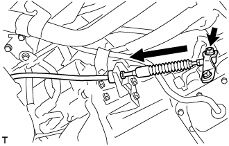
Remove a clip, nut, and disconnect between the control shaft lever to transmission control cable assembly from the control shaft lever and transmission control cable bracket No. 1.
-
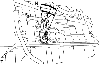
Turn the control shaft lever until stop to a clockwise direction, return the control shaft lever 2 notches to N position.
-
Set the shift lever to N position while holding the shift lever lightly toward the R position side and install it.
15 N*m 150 kgf*cm 11 ft.*lbf -
Inspect the operation condition and work.
-
- Click here
INSPECT SHIFT LEVER POSITION
-
When shifting from P position only with ignition switch ON and depress the break pedal.
-
Make sure that the shifting lever moves smoothly and can be moderately operated.
-
When starting engine, make sure that the vehicle moves forward when shifting from N to D position and moves reward when shifting R position.
-
- Click here
INSTALL NO. 1 ENGINE UNDER COVER
-
Install the No. 1 engine under cover with the 4 bolts.
13 N*m 133 kgf*cm 10 ft.*lbf
-