СВЕЧА НАКАЛИВАНИЯ УСТАНОВКА

-
INSTALL GLOW PLUG
-
Using a deep socket wrench (12 mm), install the 4 glow plugs.
- Torque:
- 13 N*m { 133 kgf*cm, 10 ft.*lbf }
-
-
INSTALL GLOW PLUG NO.1 CONNECTOR
-
Install the glow plug No.1 connectors with the 4 nuts.
- Torque:
- 2.2 N*m { 22 kgf*cm, 16 in.*lbf }
-
Install the 4 grommets.
-
-
INSTALL INTAKE MANIFOLD
-
Install a new gasket and the intake manifold with the 4 bolts and 2 nuts.
- Torque:
- 29 N*m { 296 kgf*cm, 21 ft.*lbf }
-
Install the manifold stay with the bolt and nut.
- Torque:
- 19 N*m { 194 kgf*cm, 14 ft.*lbf }
-
Connect the ground cable with the bolt.
-
-
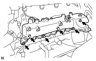
INSTALL NOZZLE LEAKAGE PIPE ASSEMBLY NO.2
-
Временно установите трубопровод обратного слива топлива и закрепите его 2 болтами.
-
Установите новую прокладку и пустотелый соединительный болт-штуцер на трубопровод обратного слива топлива.
- Torque:
- 21 Н*м { 214 кгс*см, 15 фунт-сила-футов }
-
Затяните 2 болта.
- Torque:
- 13 Н*м { 133 кгс*см, 10 фунт-сила-футов }
-
-
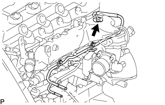
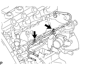
INSTALL FUEL INLET PIPE SUB-ASSEMBLY
Note
-
When replacing the fuel supply pump, common rail, cylinder block, cylinder head, cylinder head gasket, or timing gear case with a new one, replace the fuel inlet pipe.
-
Be careful not to adhere dusts, dirt or any other materials onto the joint area of the fuel inlet pipe.
-
Temporarily install the fuel inlet pipe.
-
Using SST, tighten the injection pipe on the common rail side.
- SST
- 09023-12701
- Torque:
- 32 N*m { 326 kgf*cm, 24 ft.*lbf, for use with SST }
-
Using SST, tighten the injection pipe on the supply pump side.
- SST
- 09023-12701
- Torque:
- 32 N*m { 326 kgf*cm, 24 ft.*lbf, for use with SST }
-
-
INSTALL INJECTION PIPE
- SST
- 09023-12701
Note
-
When replacing the fuel injector, common rail, or cylinder head with a new one, replace injection pipes No. 1, No. 2, No. 3, and No. 4.
-
Keep clean the joint of the injection pipe.
-
Install the injection pipes.
-
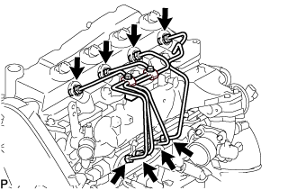
Temporarily install the 4 injection pipes.
-
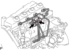
Install the injection pipe clamp No.3 in 2 nuts.
- Torque:
- 5.0 N*m { 51 kgf*cm, 44 in.*lbf }
-
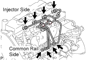
Fasten the union sequentially, from the injection pipe common rail to the injector, using SST.
- SST
- 09023-12701
- Torque:
- Use union nut wrench and torque wrench
- 32 N*m { 326 kgf*cm, 24 ft.*lbf }
-
-
INSTALL OIL LEVEL GAUGE GUIDE
-
Установите на трубку щупа проверки уровня масла новое уплотнительное кольцо.
-
Нанесите на уплотнительное кольцо тонкий слой моторного масла.
-
Установите трубку щупа проверки уровня масла и закрепите ее болтом.
- Torque:
- 8,0 Н*м { 82 кгс*см, 71 фунт-сила-дюйм }
-
Установите щуп проверки уровня масла.
-
-
INSTALL INTAKE AIR CONNECTOR (w/o EGR Valve)
-
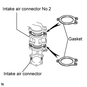
Temporarily install 2 new gaskets and intake air connector No.2 to the intake air connector.
-
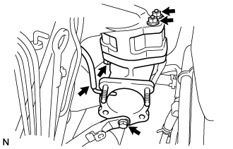
Temporarily tighten the intake air connector assembly with the bolt and 2 nuts.
-
Tighten the manifold stay with the bolt.
-
Tighten the intake air connector with the bolt and 2 nuts.
-
Install the vacuum hose to the intake air connector.
-
-
INSTALL ELECTRIC EGR CONTROL VALVE ASSEMBLY (w/ EGR Valve)
-
Temporarily tighten the EGR valve assembly with the sensor.
-
Install 2 new gaskets and the EGR valve to the intake air connector as shown in the illustration.
-
Temporarily tighten the intake air connector with EGR valve assembly to the intake manifold with the bolt and the 2 nuts.
-
Install the vacuum hose to the intake air connector.
-
Temporarily tighten the manifold stay with the bolt.
-
Connect the EGR valve position sensor connector.
-
Connect the intake air temperature sensor connector.
-
-
Install the vacuum regulating valve.
-
Install the vacuum regulating valve with the 2 bolts.
- Torque:
- 20 N*m { 204 kgf*cm, 15 ft.*lbf }
-
Connect the 2 vacuum hoses and the regulating valve connector.
-
-
-
INSTALL ENGINE SERVICE HOLE COVER NO.2
-
Install the engine service hole cover No.2 with the 3 bolts.
- Torque:
- 13 N*m { 133 kgf*cm, 10 ft.*lbf }
-
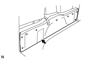
Return the carpet.
-
-
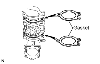
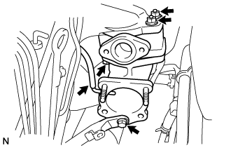
INSTALL EGR PIPE SUB-ASSEMBLY NO.1 (w/ EGR Valve)
-
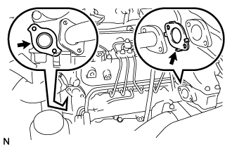
Install 2 new gaskets to the cylinder head and the EGR pipe sub-assembly No.1 as shown in the illustration.
-
Install the EGR pipe with the 2 bolts and the 2 nuts.
- Torque:
- 13 N*m { 133 kgf*cm, 10 ft.*lbf }
-
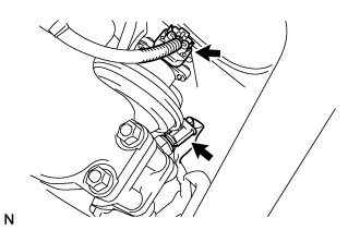
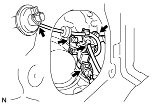
Connect the fuel pressure sensor connector.
-
-
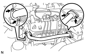
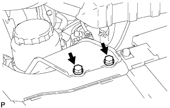
INSTALL DIESEL THROTTLE BODY ASSEMBLY
Note
After removing and installing, or replacing the throttle body, be sure to perform the operation check.
-
Install a new gasket to intake air connector.
-
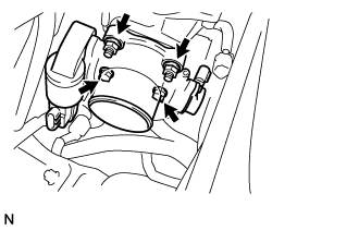
Install the throttle body with the 2 bolts and the 2 nuts.
- Torque:
- 20 N*m { 204 kgf*cm, 15 ft.*lbf }
-
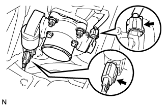
Connect the 2 throttle body connectors.
-
-
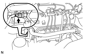
INSTALL AIR HOSE NO.4
-
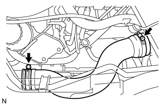
Install the air hose No.4 with the 2 clamps.
- Torque:
- 6.0 N*m { 61 kgf*cm, 53 in.*lbf }
-
-
CONNECT OIL RETURN HOSE (w/ Inter Cooler)
-
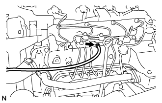
Connect the oil return hose with the clip.
-
-
INSTALL VANE PUMP OIL RESERVOIR ASSEMBLY
-
Установите масляный бачок лопастного насоса в сборе и закрепите 2 болтами.
- Torque:
- 8,0 Н*м { 82 кгс*см, 71 фунт-сила-дюйм }
-
-
INSTALL ENGINE SERVICE HOLE SUB COVER ASSEMBLY
-
Установите вспомогательную крышку технологического отверстия двигателя и закрепите ее 5 болтами.
- Torque:
- 13 Н*м { 133 кгс*см, 10 фунт-сила-футов }
-
-
INSTALL FRONT DOOR SCUFF PLATE RH
-
INSTALL FRONT SEAT ASSEMBLY RH (for Hi-back Seat Type)
-
Perform the same procedure as above on the opposite side. Click here
-
-
INSTALL FRONT SEAT ASSEMBLY RH (for Low-back Seat Type)
-
Perform the same procedure as above on the opposite side. Click here
-
-
CONNECT NEGATIVE BATTERY CABLE
-
INSPECT FUEL LEAK
-
PERFORM ACTIVE TEST
-
Connect the GTS to the DLC3.
-
Turn the ignition switch on.
-
Turn the GTS on.
-
Enter the following menus: Powertrain / Engine and ECT / Active Test.
-
Perform the Active Test.
Tester Display Test Details Control Range Diagnostic Notes Test the Fuel Leak Pressurizes common rail internal fuel pressure, and checks for fuel leaks Stop/Start
-
Fuel pressure inside common rail pressurized to specified value and engine speed increased to 2,000 rpm when ON is selected
-
Above conditions preserved while test is ON
-
-
-
-
INSPECT FUNCTION OF THROTTLE BODY
-
Inspect the throttle control motor.
-
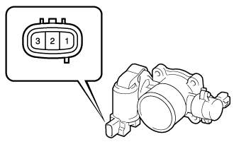
Using an ohmmeter, measure the resistance between the terminals.
Standard resistance Tester Connection Specified Condition 1 (DUTY) - Body ground Infinity
-
-
-
PERFORM INITIALIZATION
-
Some system need initialization when reconnecting the battery cable. Click here
-