МАСЛЯНЫЙ НАСОС СНЯТИЕ

-
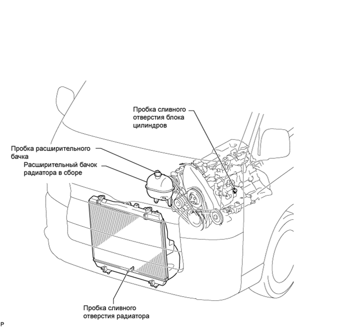
DRAIN ENGINE COOLANT
CAUTION:
Для предотвращения ожогов не снимайте пробку расширительного бачка, пока двигатель и радиатор не охладятся. Тепловое расширение вызывает выброс из радиатора горячей охлаждающей жидкости и пара.
-
Ослабьте пробку сливного отверстия радиатора.
-
Снимите пробку расширительного бачка.
-
Ослабьте пробку сливного отверстия блока цилиндров и слейте охлаждающую жидкость.
-
Затяните пробку сливного отверстия радиатора.
-
Затяните пробку сливного отверстия блока цилиндров.
- Torque:
- 13 Н*м { 130 кгс*см, 9 фунт-сила-футов }
-
-
DRAIN ENGINE OIL
Note
-
Prolonged and repeated contact with mineral oil will result in the removal of natural fats from the skin, leading to dryness, irritation and dermatitis. In addition, used engine oil contains potentially harmful contaminants which may cause skin cancer.
-
Exercise caution in order to minimize the duration and frequency of skin contact with used oil. Wear protective clothing and gloves. Wash your skin thoroughly with soap and water, or use water-less hand cleaner to remove any used engine oil. Do not use gasoline, thinners, or solvents.
-
In order to preserve the environment, used oil and the used oil filter must be disposed of only at designated disposal sites.
-
Remove the oil filler cap.
-
Remove the oil drain plug, and drain the oil into a container.
-
Clean the drain plug, and install it with a new gasket.
- Torque:
- 35 N*m { 350 kgf*cm, 25 ft.*lbf }
-
-
REMOVE FRONT SEAT ASSEMBLY RH
-
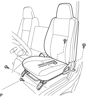
Выдвиньте переднее сиденье в сборе до упора вперед.
-
Выверните 2 болта с задней стороны сиденья.
-
Сдвиньте переднее сиденье в сборе в крайнее заднее положение.
-
Выверните 2 болта с передней стороны сиденья.
-
Сдвиньте переднее сиденье в сборе к середине направляющей сиденья. Установите спинку сиденья в вертикальное положение.
-
Отсоедините разъем замка ремня безопасности переднего сиденья.
-
Снимите переднее сиденье в сборе.
-
-
REMOVE FRONT DOOR SCUFF PLATE RH
-
REMOVE ENGINE SERVICE HOLE SUB COVER SUB-ASSEMBLY
-
Заверните коврик и снимите крышку технологического отверстия двигателя.
-
-
REMOVE RADIATOR HOSE INLET
-
REMOVE RADIATOR HOSE NO.4
-
DISCONNECT WATER HOSE (for Heater)
-
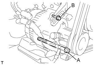
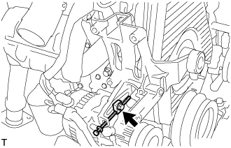
REMOVE VANE PUMP V BELT
-
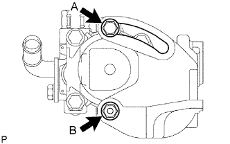
Ослабьте болт А и гайку В и снимите поликлиновой ремень.
-
-
REMOVE V (COOLER COMPRESSOR TO CRANKSHAFT PULLEY) BELT NO.1 (w/ Air Conditioning System)
-
Ослабьте гайку А и болт В и снимите поликлиновой ремень.
-
-
REMOVE FAN & GENERATOR V BELT (w/o Air Conditioning)
-
Ослабьте болты А и В и снимите поликлиновой ремень.
-
-
REMOVE FAN & GENERATOR V BELT (w/ Air Conditioning System)
-
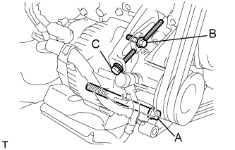
Ослабьте болты A и В.
-
Ослабьте регулировочный болт C и снимите поликлиновой ремень.
-
-
REMOVE WATER PUMP PULLEY
-
Remove the 4 nuts, fan spacer and fan pulley.
-
-
REMOVE VENTURI ASSEMBLY
-
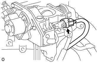
Disconnect the throttle open switch connector.
-
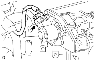
Disconnect the throttle control motor connector.
-
Remove the venturi and gasket.
-
-
SEPARATE COMPRESSOR AND MAGNETIC CLUTCH (w/ Air Conditioning System)
-
REMOVE COMPRESSOR MOUNTING BRACKET (w/ Air Conditioning System)
-
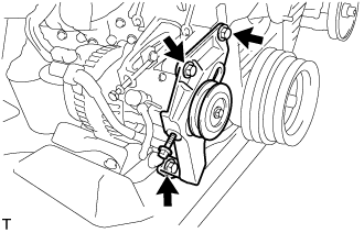
Отверните 3 болта и снимите кронштейн опоры компрессора.
-
Выверните болт и снимите распорную трубку.
-
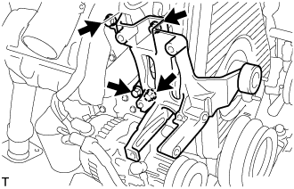
Отверните 4 болта и снимите кронштейн опоры компрессора.
-
-
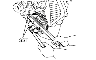
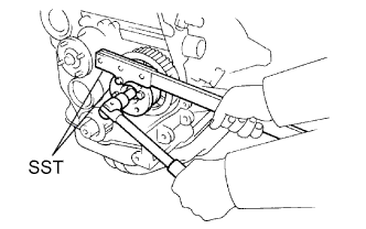
REMOVE VANE PUMP DRIVE PULLEY
-
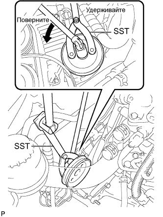
С помощью SST отверните гайку и снимите шкив лопастного насоса.
- SST
- 09960-10010 ( 09962-01000, 09963-01000 )
-
-
REMOVE CRANKSHAFT PULLEY
-
Using SST, remove the pulley bolt.
- SST
- 09213-54015 ( 91651-60855 )
- 09330-00021
-
Using SST, remove the pulley.
- SST
- 09950-50013 ( 09951-05010, 09952-05010, 09953-05020, 09954-05021 )
- 09950-60010 ( 09951-00490 )
- 09950-40011 ( 09957-04010 )
-
-
REMOVE TIMING CHAIN OR BELT COVER SUB-ASSEMBLY
-
Remove the 11 bolts, washers, timing belt cover and 2 gaskets.
-
-
REMOVE TIMING BELT GUIDE
-
Remove the timing belt guide.
-
-
SET NO.1 CYLINDER TO TDC/COMPRESSION
-
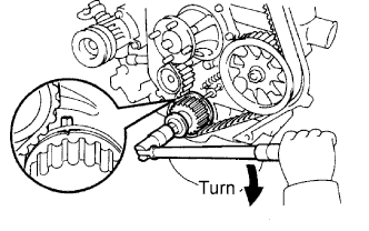
Using the crankshaft pulley bolt, align its groove with the timing pointer by turning the crankshaft clockwise.
-
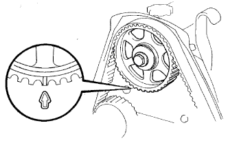
Check that the timing marks of the camshaft timing pulley and No.2 timing belt cover are aligned.
If not, turn the crankshaft 1 revolution (360°).
-
-
REMOVE TIMING BELT
-
Remove the timing belt.
Tech Tips
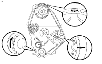
If reusing the timing belt, draw a direction arrow on the timing belt (in the direction of engine revolution), and place matchmarks on the pulleys and timing belt.
-
Turn the crankshaft 90° counterclockwise, and put the timing mark of the crankshaft timing pulley with the protrusion of the timing gear case.
Note
If the timing belt is disengaged, having the crankshaft timing pulley at the wrong angle can cause the piston head and valve head to come into contact with each other when you remove the camshaft timing pulley, causing damage. So always set the crankshaft pulley at the correct angle.
-
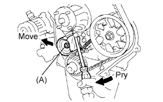
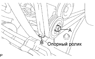
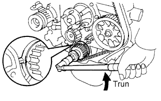
Loosen the timing belt idler No.1 bolt (A), and shift the idler to the left as far as possible.
-
Temporarily tighten the pulley bolt (A), and then relieve the timing belt tension.
-
Remove the timing belt.
-
-
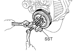
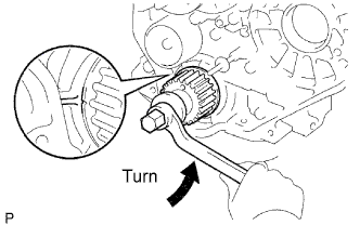
REMOVE INJECTION PUMP DRIVE PULLEY
-
Using SST, remove the pulley nut.
- SST
- 09213-14010 ( 91651-60865 )
- 09330-00021
-
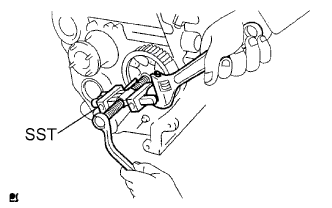
Using SST, remove the drive pulley.
- SST
- 09950-50013 ( 09951-05010, 09952-05010, 09953-05010, 09954-05021 )
-
-
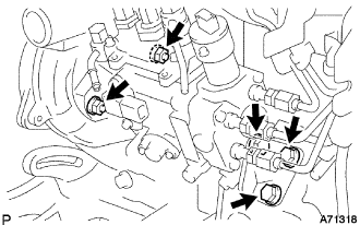
REMOVE INJECTION PUMP
-
Disconnect the engine speed sensor connector.
-
Disconnect the spill control valve connector.
-
Disconnect the correction unit connector.
-
Disconnect the timer control valve connector.
-
Disconnect the fuel temperature sensor connector.
-
Disconnect the engine wire clamp.
-
Disconnect the 3 fuel hoses.
-
Disconnect the 3 bolts and injection pump stay No.1.
-
Remove the 2 nuts and injection or supply pump assembly.
-
-
REMOVE TIMING BELT COVER NO.2
-
Remove the 4 bolts and timing belt cover.
-
-
REMOVE WATER PUMP ASSEMBLY
-
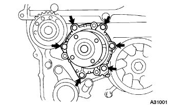
Remove the 6 bolts and tension spring bracket.
-
Remove the water pump and gasket.
-
-
REMOVE CAMSHAFT TIMING PULLEY
-
Set the No.1 cylinder to approx. 90° BTDC/compression.
Tech Tips
Set the No.1 cylinder to 90° BTDC/compression to avoid interference with the piston top and valve head.
-
Using the crankshaft pulley bolt, turn the crankshaft 90° counterclockwise, and put the timing mark of the crankshaft timing pulley with the protrusion of the timing gear case.
-
-
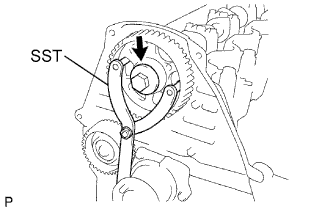
Using SST, loosen the pulley bolt.
- SST
- 09960-10010 ( 09962-01000, 09963-01000 )
-
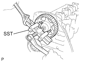
Using SST, separate the timing pulley from the camshaft.
- SST
- 09950-50013 ( 09951-05010, 09952-05010, 09953-05010, 09954-05021 )
-
Remove the pulley bolt and timing pulley.
-
Remove the timing gear woodruff key.
-
-
REMOVE TIMING BELT IDLER SUB-ASSEMBLY NO.1
-
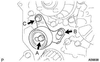
Remove the 2 bolts (A and B).
-
Loosen the bolt (C), and remove the timing belt idler No.1.
-
-
REMOVE TIMING BELT IDLER SUB-ASSEMBLY NO.2
-
Remove the bolt, timing belt idler No.2 and spacer.
-
-
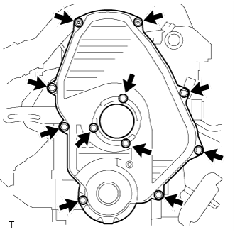
REMOVE OIL PAN SUB-ASSEMBLY
-
Remove the 16 bolts and 2 nuts.
-
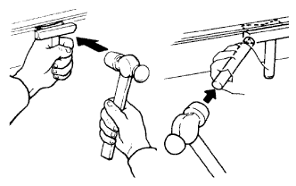
Insert the blade of a oil pan seal cutter between the oil pan and cylinder block, and cut off applied sealer and remove the oil pan.
Note
-
Do not use a oil pan seal cutter for the timing belt case side and rear oil seal retainer.
-
Be careful not to damage the oil pan flange.
-
-
-
REMOVE OIL STRAINER SUB-ASSEMBLY
-
Remove the 2 bolts, 2 nuts, oil strainer, and gasket.
-
-
REMOVE TIMING GEAR CASE SUB-ASSEMBLY
-
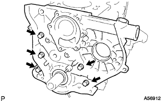
Remove the 5 bolts, timing gear case, and gasket.
-