- Click here
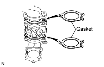
INSTALL OIL COOLER ASSEMBLY
-
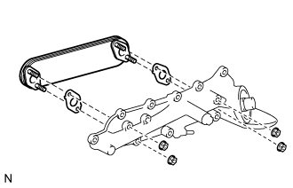
Install 2 new gaskets and oil cooler to the oil cooler cover.
-
Tighten the 4 nuts.
16 N*m 163 kgf*cm 12 ft.*lbf
-
- Click here
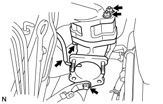
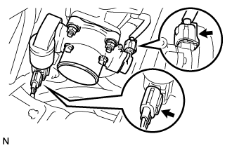
INSTALL OIL COOLER COVER SUB-ASSEMBLY (w/o EGR Valve)
-
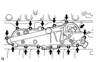
Install a new gasket and oil cooler cover with the 2 nuts and 13 bolts.
13 N*m 133 kgf*cm 10 ft.*lbf -
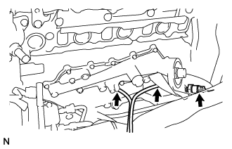
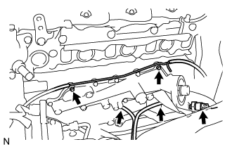
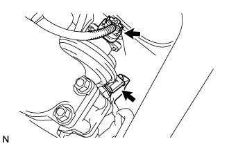
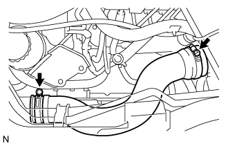
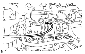
Install the oil drain hoses.
-
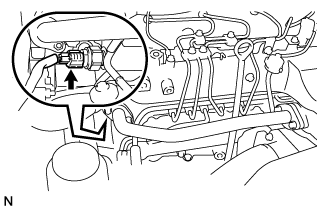
Connect the oil pressure switch connector.
-
- Click here
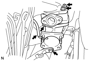
INSTALL OIL COOLER COVER SUB-ASSEMBLY (w/ EGR Valve)
-
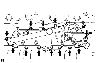
Install a new gasket and oil cooler cover with the 13 bolts.
13 N*m 133 kgf*cm 10 ft.*lbf -
Install the vacuum transmitting pipe No.2 with the 2 nuts.
13 N*m 133 kgf*cm 10 ft.*lbf -
Install the oil drain hoses.
-
Connect the oil pressure switch connector.
-
- Click here
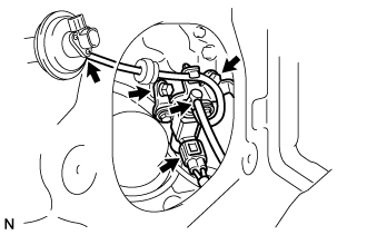
INSTALL INJECTION OR SUPPLY PUMP ASSEMBLY
-
Confirm that the supply pump gear in the timing gear case moves back and forth smoothly.
-
Install a new O-ring and the pulley key to the supply pump.
-
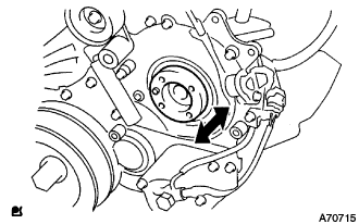
Aligning the projecting edge of the supply pump head to the key-slot of the supply pump gear, install the pump to the timing gear case.
-
While holding the supply pump by hand, push the supply pump gear rearward to engage the pump gear and drive shaft.
-
Temporarily install the supply pump with the 2 nuts.
-
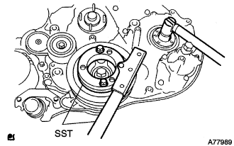
Using SST, hold the crankshaft.
09213-58013 09330-00021 -
Install the supply pump gear set nut.
Tip:Set a new O-ring before tightening the supply pump gear set nut.
64 N*m 653 kgf*cm 47 ft.*lbf -
Temporarily install the supply pump stay with the 2 bolts on the engine block side.
-
Tighten the 2 nuts for the injection pump.
21 N*m 214 kgf*cm 16 ft.*lbf -
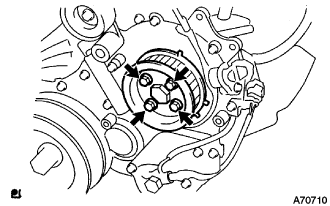
Install the camshaft timing pulley flange No.2 and pump drive shaft pulley with the 4 bolts.
31 N*m 316 kgf*cm 23 ft.*lbf
-
- Click here
CHECK PUMP DRIVE SHAFT THRUST CLEARANCE
-
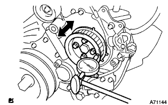
Push the pump drive shaft pulley back and forth to check a thrust clearance of the injection pump drive shaft.
Thrust clearance 0.15 to 0.55 mm (0.0059 to 0.0217 in.) Note:Make sure that the crankshaft pulley's notch is at 30 degree in the counterclockwise direction form the TDC position.
Tip:If there is not thrust clearance, disassemble and reassemble the injection pump and pump drive shaft pulley.
-
- Click here
INSTALL COMMON RAIL ASSEMBLY
-
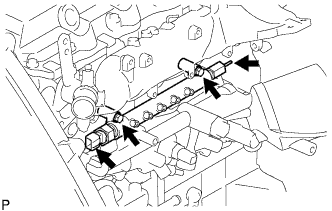
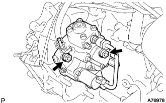
Install the common rail assembly with the 2 bolts.
38 N*m 387 kgf*cm 28 ft.*lbf -
Connect the fuel hose to the fuel pressure limiter.
-
Connect the fuel pressure sensor connector.
-
- Click here
INSTALL OIL FILTER SUB-ASSEMBLY
- Click here
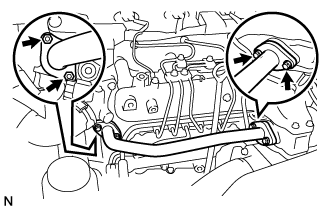
INSTALL INTAKE MANIFOLD
-
Install a new gasket and the intake manifold with the 4 bolts and 2 nuts.
29 N*m 296 kgf*cm 21 ft.*lbf -
Install the manifold stay with the bolt and nut.
19 N*m 194 kgf*cm 14 ft.*lbf -
Connect the ground cable with the bolt.
-
- Click here
INSTALL NOZZLE LEAKAGE PIPE ASSEMBLY NO.2
-
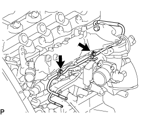
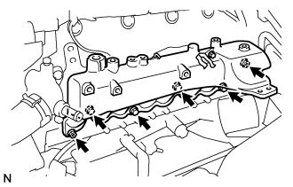
Temporarily install the nozzle leakage pipe assembly No.2 with the 2 bolts.
-
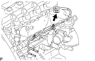
Install the check valve nozzle leakage pipe assembly No.2 and a new gasket.
21 N*m 214 kgf*cm 15 ft.*lbf -
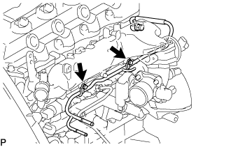
Tighten the 2 bolts.
13 N*m 133 kgf*cm 10 ft.*lbf -
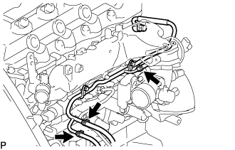
Install the 3 fuel hoses on the nozzle leakage pipe assembly No.2.
-
- Click here
INSTALL FUEL INLET PIPE SUB-ASSEMBLY
Note:
-
When replacing the fuel supply pump, common rail, cylinder block, cylinder head, cylinder head gasket, or timing gear case with a new one, replace the fuel inlet pipe.
-
Be careful not to adhere dusts, dirt or any other materials onto the joint area of the fuel inlet pipe.
-
Temporarily install the fuel inlet pipe.
-
Using SST, tighten the injection pipe on the common rail side.
09023-12701 32 N*m 326 kgf*cm 24 ft.*lbf for use with SST -
Using SST, tighten the injection pipe on the supply pump side.
09023-12701 32 N*m 326 kgf*cm 24 ft.*lbf for use with SST
-
- Click here
INSTALL INJECTION PIPE SUB-ASSEMBLY
09023-12701 Note:
-
When replacing the fuel injector, common rail, or cylinder head with a new one, replace injection pipes No. 1, No. 2, No. 3, and No. 4.
-
Keep clean the joint of the injection pipe.
-
Install the injection pipes.
-
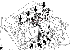
Temporarily install the 4 injection pipes.
-
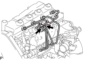
Install the injection pipe clamp No.3 in 2 nuts.
5.0 N*m 51 kgf*cm 44 in.*lbf -
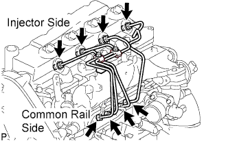
Fasten the union sequentially, from the injection pipe common rail to the injector, using SST.
09023-12701 Use union nut wrench and torque wrench 32 N*m 326 kgf*cm 24 ft.*lbf
-
-
- Click here
INSTALL OIL LEVEL GAUGE GUIDE
-
Установите на трубку щупа проверки уровня масла новое уплотнительное кольцо.
-
Нанесите на уплотнительное кольцо тонкий слой моторного масла.
-
Установите трубку щупа проверки уровня масла и закрепите ее болтом.
8,0 Н*м 82 кгс*см 71 фунт-сила-дюйм -
Установите щуп проверки уровня масла.
-
- Click here
INSTALL INTAKE AIR CONNECTOR (w/o EGR Valve)
-
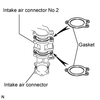
Temporarily install 2 new gaskets and intake air connector No.2 to the intake air connector.
-
Temporarily tighten the intake air connector assembly with the bolt and 2 nuts.
-
Tighten the manifold stay with the bolt.
-
Tighten the intake air connector with the bolt and 2 nuts.
-
Install the vacuum hose to the intake air connector.
-
- Click here
TEMPORARILY TIGHTEN ELECTRIC EGR CONTROL VALVE ASSEMBLY (w/ EGR Valve)
-
Temporarily tighten the EGR valve assembly with the sensor.
-
Install 2 new gaskets and the EGR valve to the intake air connector as shown in the illustration.
-
Temporarily tighten the intake air connector with EGR valve assembly to the intake manifold with the bolt and the 2 nuts.
-
Install the vacuum hose to the intake air connector.
-
Temporarily tighten the manifold stay with the bolt.
-
Connect the EGR valve position sensor connector.
-
Connect the intake air temperature sensor connector.
-
-
Install the vacuum regulating valve.
-
Install the vacuum regulating valve with the 2 bolts.
20 N*m 204 kgf*cm 15 ft.*lbf -
Connect the 2 vacuum hoses and the regulating valve connector.
-
-
- Click here
INSTALL EGR PIPE SUB-ASSEMBLY NO.1 (w/ EGR Valve)
-
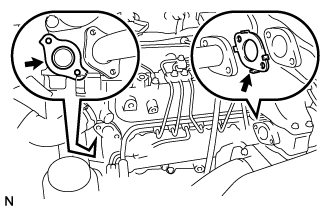
Install the 2 gaskets to the cylinder head and EGR pipe sub-assembly as shown in the illustration.
-
Install the EGR pipe sub-assembly with the 2 bolts and 2 nuts.
13 N*m 133 kgf*cm 10 ft.*lbf -
Tighten the intake air connector with the bolt and the 2 nuts.
20 N*m 204 kgf*cm 15 ft.*lbf -
Tighten the manifold stay.
19 N*m 194 kgf*cm 14 ft.*lbf
-
- Click here
INSTALL EGR PIPE SUB-ASSEMBLY NO.1 (w/ EGR Valve)
-
Install the 2 gaskets to the cylinder head and EGR pipe sub-assembly as shown in the illustration.
-
Install the EGR pipe sub-assembly with the 2 bolts and 2 nuts.
13 N*m 133 kgf*cm 10 ft.*lbf -
Tighten the intake air connector with the bolt and the 2 nuts.
20 N*m 204 kgf*cm 15 ft.*lbf -
Tighten the manifold stay.
19 N*m 194 kgf*cm 14 ft.*lbf
-
- Click here
INSTALL DIESEL THROTTLE BODY ASSEMBLY
Note:After removing and installing, or replacing the throttle body, be sure to perform the operation check.
-
Install a new gasket to intake air connector.
-
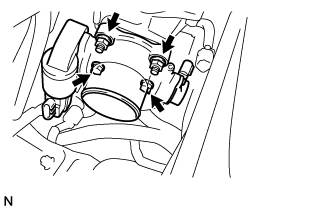
Install the throttle body with the 2 bolts and the 2 nuts.
20 N*m 204 kgf*cm 15 ft.*lbf -
Connect the 2 throttle body connectors.
-
- Click here
INSTALL AIR HOSE NO.4
-
Install the air hose No.4 with the 2 clamps.
6.0 N*m 61 kgf*cm 53 in.*lbf
-
- Click here
INSTALL EGR PIPE SUB-ASSEMBLY NO.1 (w/ EGR Valve)
-
Install 2 new gaskets to the cylinder head and the EGR pipe sub-assembly No.1 as shown in the illustration.
-
Install the EGR pipe with the 2 bolts and the 2 nuts.
13 N*m 133 kgf*cm 10 ft.*lbf -
Connect the fuel pressure sensor connector.
-
- Click here
CONNECT OIL RETURN HOSE (w/ Intercooler)
-
Connect the oil return hose with the clip.
-
- Click here
INSTALL TIMING BELT
-
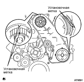
Удостоверьтесь, что установочные метки совмещены, как показано на рисунке.
-
Установите приводной ремень газораспределения на шкив приводного вала насоса, зубчатое колесо распредвала и опорный ролик приводного ремня газораспределения № 1, придерживаясь этой последовательности.
-
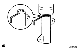
Установите натяжитель вертикально на пресс.
Note:
-
Не допускайте царапания и деформирования конца толкателя.
-
Запрессуйте толкатель натяжителя.
-
Обеспечьте защиту конца толкателя от повреждений ветошью.
-
-
С помощью пресса медленно запрессуйте толкатель с усилием 981 - 9807 Н (100 - 1000 кгс, 220 - 2205 фунт-силы).
Note:Не прикладывайте к толкателю усилие свыше 981 - 9807 Н (100 - 1000 кгс, 220 - 2205 фунт-силы).
-
Совместите отверстия в толкателе и кожухе. Для сохранения положения установки толкателя пропустите через отверстия шестигранную головку на 1,27 мм.
-
Временно закрепите натяжитель приводного ремня 2 болтами, прижимая опорный ролик к приводному ремню газораспределения.
-
Затяните 2 болта.
13 Н*м 133 кгс*см 10 фунт-сила-футов Note:Равномерно затяните 2 болта и установите натяжитель
-
Выньте из натяжителя торцевой гаечный ключ на 1,5 мм.
-
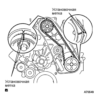
Поверните коленчатый вал по часовой стрелке на два оборота и убедитесь, что установочные метки совмещены, как показано на рисунке.
-
- Click here
INSTALL TIMING BELT COVER NO.1
-
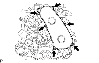
Установите крышку приводного ремня газораспределения № 1 и закрепите ее 6 болтами.
6,0 Н*м 61 кгс*см 53 фунт-сила-дюйма -
Присоедините зажим жгута проводов.
-
- Click here
INSTALL FAN & GENERATOR V BELT
-
Провернув шкив натяжителя поликлинового ремня по часовой стрелке, установите поликлиновой ремень вентилятора и генератора.
Note:Проверьте правильность посадки поликлинового ремня вентилятора и генератора на каждом шкиве.
-
Проверьте метку индикатора натяжителя поликлинового ремня (см. стр.Click here).
-
- Click here
INSTALL VANE PUMP OIL RESERVOIR ASSEMBLY
-
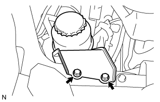
Install the vane pump oil reservoir assembly with the 2 bolts.
8.0 N*m 82 kgf*cm 71 in.*lbf
-
- Click here
ADD ENGINE COOLANT
-
Надежно затяните сливные пробки.
-
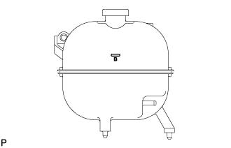
Залейте охлаждающую жидкость в расширительный бачок радиатора до верха горловины.
Номинальный объем Параметр / Устройство Заданные условия Для моделей без подогревателя 13,2 литра (13,9 кварты США, 11,6 английской кварты) Для моделей с передним подогревателем 14,2 литра (15,0 кварты США, 12,5 английской кварты) Для моделей с передним и задним подогревателями 16,2 л (17,1 кварты США, 14,3 английской кварты) Note:Не доливайте простую воду вместо охлаждающей жидкости двигателя.
Tip:
-
Использование неподходящей охлаждающей жидкости может привести к повреждению системы охлаждения двигателя.
-
Разрешается использовать только охлаждающую жидкость "TOYOTA Super Long Life Coolant" или аналогичную высококачественную охлаждающую жидкость на основе этиленгликоля (а не на силикатной, аминовой, нитритной или борнокислой основе), изготовленную по гибридной технологии органических кислот с длительным сроком годности (охлаждающая жидкость, изготовленная по гибридной технологии органических кислот, состоит из низкофосфатных соединений и органических кислот).
-
-
Ослабьте прокачной штуцер корпуса отводящего патрубка.
-
После удаления воздуха и слива охлаждающей жидкости двигателя надежно затяните прокачной штуцер.
8,0 Н*м 82 кгс*см 71 фунт-сила-дюйм -
Долейте охлаждающую жидкость в расширительный бачок радиатора до отметки B и установите пробку расширительного бачка радиатора.
-
Прогревайте двигатель, пока не откроется термостат.
-
Когда термостат откроется, несколько минут прокачивайте охлаждающую жидкость двигателя.
Tip:Время открывания термостата можно проверить, сжав шланг радиатора № 3 рукой и определив, когда охлаждающая жидкость начинает поступать в шланг.
-
-
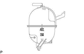
После охлаждения двигателя убедитесь, что уровень охлаждающей жидкости двигателя находится между отметками "LOW" и "FULL".
-
- Click here
CONNECT CABLE TO NEGATIVE BATTERY TERMINAL
- Click here
INSTALL BATTERY SERVICE HOLE COVER
- Click here
BLEED FUEL LINE
-
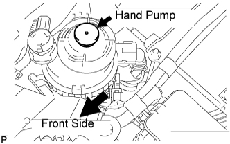
Using the hand pump, bleed air from the fuel system until pumping becomes difficult.
-
- Click here
CHECK FOR ENGINE OIL LEAKS
- Click here
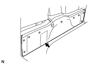
INSTALL ENGINE SERVICE HOLE COVER NO.2
-
Install the engine service hole cover No.2 with the 3 bolts.
13 N*m 133 kgf*cm 10 ft.*lbf -
Return the carpet.
-
- Click here
INSTALL ENGINE SERVICE HOLE SUB COVER SUB-ASSEMBLY
-
Установите вспомогательную крышку технологического отверстия двигателя и закрепите ее 5 болтами.
13 Н*м 133 кгс*см 10 фунт-сила-футов
-
- Click here
INSTALL FRONT SEAT ASSEMBLY RH (for Hi-back Seat Type)
- Click here
INSTALL FRONT SEAT ASSEMBLY RH (for Low-back Seat Type)
- Click here
INSTALL FRONT DOOR SCUFF PLATE RH
- Click here
INSTALL ENGINE UNDER COVER NO.1 (w/ Engine Under Cover No.1)
13 Н*м 133 кгс*см 10 фунт-сила-футов - Click here
PERFORM INITIALIZATION