СИСТЕМА ВЕНТИЛЯТОРА СИСТЕМЫ ОХЛАЖДЕНИЯ ПРОВЕРКА БЕЗ СНЯТИЯ С АВТОМОБИЛЯ
-
INSPECT COOLING FAN SYSTEM
-
Put the vehicle in the following conditions:
-
Turn the ignition switch off.
-
The coolant temperature is less than 79°C (174°F).
-
The battery voltage is between 9 and 14 V.
-
The A/C switch is off.
-
-
Clamp the 400 A probe of an ammeter over the M+ wire of each cooling fan motor.
-
Turn the ignition switch to ON and wait for approximately 10 seconds. Check that the fans stop.
-
Start the engine. Check that the fans stop with the engine idling.
Tech Tips
Make sure that the radiator coolant temperature is less than 79°C (174°F) and the A/C switch is off.
-
Check that the fan operates when the A/C switch is turned on (MAX COOL and the magnetic clutch is operating).
Standard Current Item Specified Condition No. 1 cooling fan motor 4 to 23 A No. 2 cooling fan motor 4 to 23 A Tech Tips
The coolant temperature is less than 79°C (174°F).
-
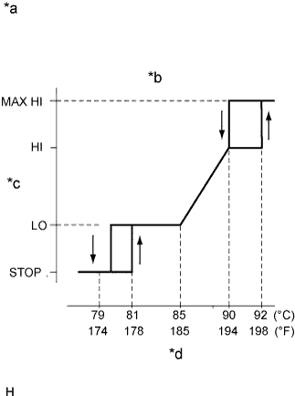
Text in Illustration *a Operating Diagram *b A/C Off *c Fan Speed *d Engine Coolant Temperature After the engine is warmed up, check that the fan operates as shown in the illustration.
Tech Tips
-
The coolant temperature at which the fan starts operating is approximately 81°C (178°F).
-
This system can also be checked using the intelligent tester.
-
Enter the following menus: Powertrain / Engine / Data List / Initial Engine Coolant Temp.
-
-
-
INSPECT COOLING FAN ECU
-
Check the input voltage.
-
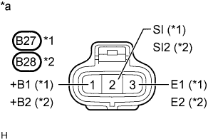
Text in Illustration *1 No. 1 Cooling Fan ECU *2 No. 2 Cooling Fan ECU *a Front view of wire harness connector
(to No. 1 or No. 2 Cooling Fan ECU)
Disconnect the No. 1 and No. 2 cooling fan ECU connectors.
-
Turn the ignition switch to ON.
-
Measure the voltage according to the value(s) in the table below.
Standard Voltage Tester Connection Condition Specified Condition B27-1 (+B1) - B27-3 (E1) Ignition switch to ON 9 to 14 V B28-1 (+B2) - B28-3 (E2) If the result is not as specified, inspect the power source system (fusible link, fuse, wire harness, relay).
-
-
Connect the No. 1 and No. 2 cooling fan ECU connectors.
-
Inspect the cooling fan motor Click here.
-
Inspect the wire harness.
-
Disconnect the ECM connector.
-
Disconnect the No. 1 and No. 2 cooling fan ECU connectors.
-
Check continuity and the insulation condition between terminal RFC of the ECM and terminal SI (SI2) of the cooling fan ECU.
Tech Tips
If the fan does not operate, there may be a short circuit. If the fan remains operating, there may be an open circuit.
-
Connect the ECM connector.
-
Connect the No. 1 and No. 2 cooling fan ECU connectors.
-
Inspect the ECM power source circuit and ground circuit.
-
-
Inspect the input signal and output current.
Note
Be sure to perform the inspection with the radiator coolant temperature less than 79°C (174°F).
-
Clamp the 400 A probe of the ammeter to the M+ terminals of the No. 1 and No. 2 cooling fan motor.
-
Set the intelligent tester to the oscilloscope function.
-
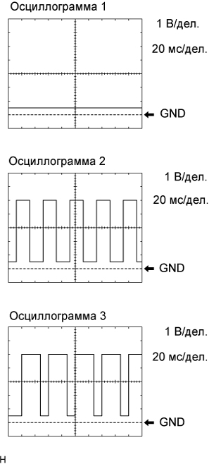
Using the intelligent tester, check the waveform between terminals RFC and E1 (E2) of the ECM.
Standard Waveform Condition Input Signal Output Current Engine stopped
Ignition switch ON
Waveform 1
(Duty ratio 0%)
(Fan stops) Engine idling
A/C OFF
Waveform 1
(0%)
(Fan stops) Engine idling
A/C ON
Waveform 2
(40 to 70%)
4 to 23 A
(Fan operates)
Engine idling and ECT sensor connector disconnected Waveform 3
(70%)
8 to 24 A
(Fan operates)
Tech Tips
-
If the input signal is abnormal, there is a malfunction in the ECM or cooling fan ECU.
-
If the output current is abnormal, there is a malfunction in the cooling fan ECU or motor.
-
-
-