ВЕНТИЛЯТОР СИСТЕМЫ ОХЛАЖДЕНИЯ ПРОВЕРКА БЕЗ СНЯТИЯ С АВТОМОБИЛЯ
-
INSPECT COOLING FAN SYSTEM
-
Put the vehicle in the following state:
-
The ignition switch is off.
-
The coolant temperature is less than 74°C (165°F).
-
The battery voltage is between 11 and 14 V.
-
The A/C switch is off.
-
-
Turn the ignition switch to ON (engine off) and wait for approximately 10 seconds. Check that the fans do not operate.
-
Start the engine. Check that the fans do not operate with the engine idling.
Tech Tips
-
Make sure that the radiator coolant temperature is less than 74°C (165°F), and that the A/C switch is off.
Check that the fans operate when the A/C switch is turned on (The temperature is set to MAX COOL and the magnet clutch is operating).
-
-
Check that the fans operate when the coolant sensor connector is disconnected.
-
After the engine has warmed up, the fan operates as shown in the illustration.
-
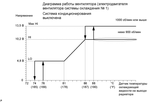
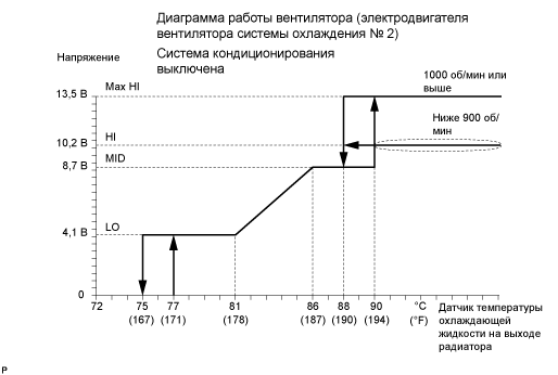
Tech Tips
-
No. 1 cooling fan motor:
The coolant temperature at which the fans start to operate is approximately 76°C (169°F).
-
No. 2 cooling fan motor:
The coolant temperature at which the fans start to operate is approximately 77°C (171°F).
-
This system can also be checked using the GTS.
-
Enter the following menus: Powertrain / Engine and ECT / Data List / Initial Engine Coolant Temp.
-
-
-
-
INSPECT NO. 1 COOLING FAN MOTOR
-
Check the input voltage.
-
Disconnect the No. 1 cooling fan motor connector.
-
Turn the ignition switch to ON.
-
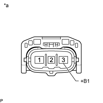
Text in Illustration *a Front view of wire harness
(to No. 1 Cooling Fan connector)
Measure the voltage according to the value(s) in the table below.
Standard Voltage Tester Connection Switch Condition Specified Condition B90-3 (+B1) - Body ground Ignition switch ON 11 to 14 V -
If the terminal voltage is not within the specification, inspect the power source system (fusible link, fuse, wire harness and relay).
-
-
Inspect the wire harness.
-
Disconnect the ECM and No. 1 cooling fan motor connectors.
-
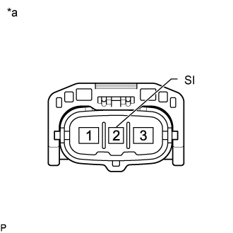
Text in Illustration *a Front view of wire harness
(to No. 1 Cooling Fan connector)
Measure the resistance according to the value(s) in the table below.
Standard Resistance Tester Connection Specified Condition B97-60 (RFC) - B90-2 (SI) Below 1Ω Tech Tips
If the fan does not operate, there may be a short circuit. If the fan remains operating, there may be an open circuit.
-
Inspect the ECM power source circuit and ground circuit.
-
-
Inspect the input signal.
Note
-
Be sure to perform the inspection with the radiator coolant temperature less than 74°C (165°F).
-
Set the oscilloscope.
-
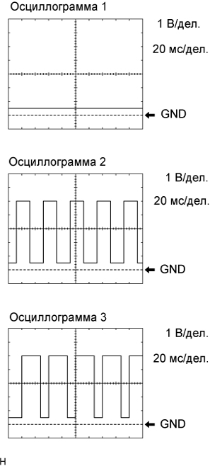
Using the oscilloscope, check the waveform between No. 1 cooling fan motor terminals E1 and SI.
Standard Condition Input Signal Engine stopped
IG switch ON
Waveform 1
(Duty ratio 0%)
Engine idling
A/C OFF
Waveform 1
(0%)
Engine idling
A/C ON
Waveform 2
(45 to 70%)
Engine idling and ECT sensor connector disconnected Waveform 3
(70%)
Tech Tips
If the input signal is abnormal, there is a malfunction in the ECM or cooling fan motor.
-
-
-
INSPECT NO. 2 COOLING FAN MOTOR
-
Check the input voltage.
-
Disconnect the No. 2 cooling fan motor connector.
-
Turn the ignition switch to ON.
-
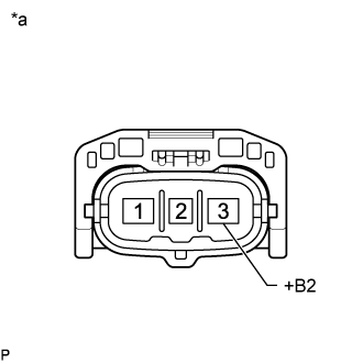
Text in Illustration *a Front view of wire harness
(to No. 2 Cooling Fan connector)
Measure the voltage according to the value(s) in the table below.
Standard Voltage Tester Connection Switch Condition Specified Condition B91-3 (+B2) - Body ground Ignition switch ON 11 to 14 V -
If the terminal voltage is not within the specification, inspect the power source system (fusible link, fuse, wire harness and relay).
-
-
Inspect the wire harness.
-
Disconnect the ECM and No. 2 cooling fan motor connectors.
-
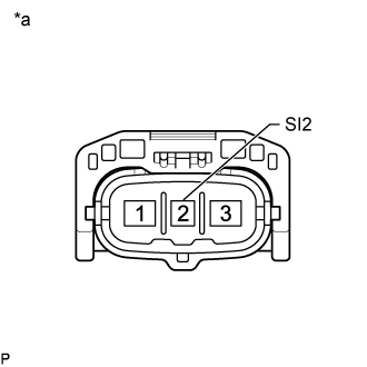
Text in Illustration *a Front view of wire harness
(to No. 2 Cooling Fan connector)
Measure the resistance according to the value(s) in the table below.
Standard Resistance Tester Connection Specified Condition B97-58 (RFC2) - B91-2 (SI2) Below 1Ω Tech Tips
If the fan does not operate, there may be a short circuit. If the fan remains operating, there may be an open circuit.
-
Inspect the ECM power source circuit and ground circuit.
-
-
Inspect the input signal.
Note
-
Be sure to perform the inspection with the radiator coolant temperature less than 74°C (165°F).
-
Set the oscilloscope.
-
Using the oscilloscope, check the waveform between No. 2 cooling fan motor terminals E2 and SI2.
Standard Condition Input Signal Engine stopped
IG switch ON
Waveform 1
(Duty ratio 0%)
Engine idling
A/C OFF
Waveform 1
(0%)
Engine idling
A/C ON
Waveform 2
(40 to 60%)
Engine idling and ECT sensor connector disconnected Waveform 3
(70%)
Tech Tips
If the input signal is abnormal, there is a malfunction in the ECM or cooling fan motor.
-
-