ТУРБОНАГНЕТАТЕЛЬ ОПИСАНИЕ СИСТЕМЫ
This section should be used as a guide for troubleshooting when the turbocharger is suspected as the cause of a problem.
-
OUTLINE OF TURBOCHARGER FAILURE
-
State of Turbocharger Failure Repair:
It is well known that turbocharger malfunctions cause many symptoms as shown below. However, the mechanisms resulting in these symptoms that indicate turbocharger malfunctions are not well understood. As a result, many unnecessary turbocharger replacements and other repairs are being performed due to lack of knowledge about the turbocharger and turbocharger failure. Therefore, knowing the facts regarding turbocharger malfunctions is useful for making effective repairs and saving time.
-
Turbocharger Failure Classification
Symptom Symptom Description See page Noise Whistling noise Continuous high pitch noise proportional to engine speed
-
"NOISE" listed below
-
Flowchart "Turbocharger Noise" Click here
Whining noise Relatively low pitch noise compared to whistling noise Oil leak External oil leak Oil leak on surface of turbocharger visible from outside of turbocharger
-
"OIL LEAK AND WHITE SMOKE" listed below
-
Flowchart "Turbocharger Oil Leak and White Smoke" Click here
Internal oil leak Oil leak from inside of bearing housing to inside of either compressor housing or turbine housing through seal ring White smoke Oil smoke Oil smoke is emitted from exhaust pipe Unburned fuel smoke Unburned fuel smoke is emitted from exhaust pipe Black smoke Black smoke is emitted from exhaust pipe
-
"BLACK SMOKE" listed below
-
Flowchart "Black Smoke Emitted" Click here
Lack of power or hesitation Vehicle does not reach target speed
-
"LACK OF POWER AND HESITATION" listed below
-
Flowchart "Lack of Power or Hesitation" Click here
Poor acceleration Shock during acceleration Tech Tips
This table shows only typical problems related to the turbocharger.
-
-
-
NOISE
Description Probable Cause Probable Failed Component Turbine shaft imbalance Turbocharger Leakage from intake line Intake line Gear noise
(Mistaken for turbocharger noise)
-
Gear inside engine
-
Transmission gear
-
Vacuum pump gear
Tech Tips
It is easy to confirm whether the turbocharger is the cause of the noise or not, and confirming this before inspecting the turbocharger or removing it from the engine is an effective way to reduce troubleshooting time.
-
Disconnect the actuator hose from the compressor housing.
-
Stop up the compressor housing side tube with a hose clip or equivalent.
-
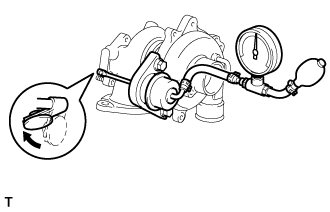
Using SST, apply pressure to the actuator to open the waste gate valve.
- SST
- 09992-00242
Note
Never apply more than predetermined maximum pressure*to the actuator.
Tech Tips
*: Valve opening pressure and predetermined maximum pressure above differ according to the vehicle model and turbocharger. For the specifications, see attached table below.
Specifications: Engine Type Turbocharger Sub-assembly
(Part No.)
Valve Opening Pressure
(kPa: Gauge Pressure)
Maximum Pressure
(kPa: Gauge Pressure)
Reference:
Rod Stroke
(mm)
2KD-FTV 17201-30070 130 147.8 0.89 to 1.74 17201-30080 119 136 0.98 to 1.91 -
Check that the actuator rod moves and that the waste gate valve opens.
-
Start the engine and allow it to idle.
-
Rev the engine up several times, depressing the accelerator pedal.
Note
Do not accelerate the engine while sufficient pressure is not applied to the actuator. The boost pressure (turbocharged air pressure) may exceed the prescribed booster pressure limit and the engine may be damaged due to overboost.
-
Check whether the noise is reduced or not compared with the noise under the original conditions.
Result Result Cause of Noise The noise is reduced (or disappears) Turbocharger The noise does not change Not turbocharger (other parts) -
Reconnect the actuator hose to the compressor housing.
Tech Tips
Refer to the flowchart "Turbocharger Noise" Click here.
-
-
OIL LEAK AND WHITE SMOKE
Description Oil Leak Type Description Main Trouble Area Internal oil leak
(White smoke)
-
Oil leak from bearing housing to either compressor housing (intake side) or turbine housing (exhaust side) through seal rings.
-
This type of oil leak is not visible from outside of turbocharger.
-
If oil leak occurs from turbine side seal, large amount of white smoke is emitted from exhaust pipe.
-
Compressor side seal ring
-
Turbine side seal ring
-
Clogging of oil drain
-
Shaft breakage
-
Shaft or bearing seizure
-
Compressor impeller damage
External oil leak
-
Oil leak from inside of turbocharger to outside of turbocharger.
-
Includes oil leaks visible from outside of turbocharger.
-
FIPG sealing part
-
Oil pipe flange
-
Oil pipe union
-
Hose connection of intake pipe
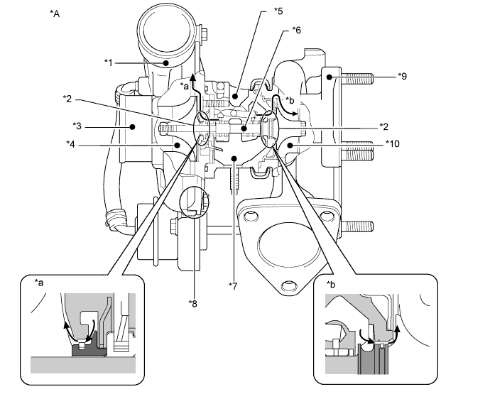
Text in Illustration *A
Waste Gate Type Turbocharger - - *1
Compressor Housing *2
Seal Ring *3
Compressor Inlet *4
Compressor Impeller *5
Bearing Housing *6
Turbine Shaft *7
Oil Drain (Outlet) *8
FIPG Sealing Part *9
Turbine Housing *10
Turbine Wheel *a
Internal oil leak to compressor housing *b
Internal oil leak to turbine housing Tech Tips
-
Above illustration is an example.
-
When there is an internal oil leak, white smoke is emitted from the exhaust pipe and oil is consumed excessively. However, the cause of white smoke or excessive oil consumption can vary. Therefore, do not assume that the turbocharger is the cause of the failure when there is white smoke emission or excessive oil consumption.
-
When there is an external oil leak, the sources of the oil leak are limited to the points mentioned in the table above. If oil leaks from a FIPG sealing part, replace the turbocharger. If oil leaks from an oil pipe flange or a hose connection, do not replace the turbocharger, but confirm and repair the flange or hose.
-
Refer to the flowchart "Turbocharger Oil Leak and White Smoke" Click here.
-
-
BLACK SMOKE
-
Malfunctions are classified into 2 types as shown below.
Description Malfunction Main Fault Intake air volume shortage Insufficient mass air flow due to, for example, excessively low boost pressure, which results in fuel injection volume being relatively excessive with respect to mass air flow. Excessive injection volume Excessive injection volume or incorrect injection timing due to fuel system trouble. -
Main Components Related to Black Smoke:
Possible Faulty Component Main Fault Turbocharger Abnormally low boost pressure Intake system Leakage between turbocharger and intake manifold Fuel system
-
Excessive fuel injection volume
-
Incorrect fuel injection timing
EGR valve Stuck or does not close completely Diesel throttle Stuck or does not move smoothly Tech Tips
The components listed above are only the main ones. Not all the components potentially related to black smoke are listed. For details regarding the troubleshooting of black smoke, refer to the flowchart "Black Smoke Emitted" Click here.
-
-
Relation between Turbocharger and Black Smoke:
If the boost pressure is lower than normal due to a turbocharger failure, black smoke may occur due to a lack of mass air flow. However, abnormally low boost pressure can be caused by the failure of various components such as intake lines, the EGR valve, etc. Therefore, do not assume that the turbocharger is the cause of abnormally low boost pressure, but check all the components possibly related to abnormally low boost pressure. Components related to abnormal boost pressure are shown in a chart listed in the On-vehicle Inspection for Intake System Click here. For simple and effective troubleshooting, refer to the chart before starting troubleshooting.
-
-
LACK OF POWER AND HESITATION
-
Malfunctions are classified into 2 types as shown below.
Description Malfunction Main Fault Intake air volume shortage Insufficient mass air flow due to, for example, excessively low boost pressure, which results in fuel injection volume being restricted. Abnormal injection volume Abnormal injection volume or timing due to fuel system trouble. -
Main Components Related to Lack of Power and Hesitation:
Possible Faulty Component Main Fault Turbocharger
-
Abnormal boost pressure
-
Waste gate valve does not move smoothly (stuck open)
Intake system
-
Leakage between turbocharger and intake manifold
-
Clogging or blockage of intake line
Fuel system
-
Abnormal injection volume
-
Incorrect fuel injection timing
EGR valve Stuck or does not close completely Diesel throttle Stuck or does not move smoothly Exhaust system Clogging of exhaust line Tech Tips
-
The components listed above are only the main ones. Not all the components potentially related to lack of power and hesitation are listed. For details regarding the troubleshooting of lack of power and hesitation, refer to the flowchart "Lack of Power and Hesitation" Click here.
-
If obvious malfunction (lack of power) has not been reproduced, perform test driving another vehicle, which is the same model and has the same engine, and compare the engine conditions and performance. If a great difference does not present in engine performance, explain to the customer that lack of power the customer mentioned is not abnormal.
-
-
Relation between Turbocharger and Abnormal Boost Pressure:
If the boost pressure is lower than normal due to a turbocharger failure, lack of power could occur due to an intake air volume shortage. However, abnormal boost pressure can be caused by the failure of various components such as intake lines, the EGR valve, etc. Therefore, do not assume that the turbocharger is the cause of abnormal boost pressure, but check all the components possibly related to abnormal boost pressure. Components related to abnormal boost pressure are shown in a chart listed in the On-vehicle Inspection for Intake System Click here. For simple and effective troubleshooting, refer to the chart before starting troubleshooting.
-
-
MIL TURNS ON
If a DTC related to a turbocharger malfunction is stored, refer to the troubleshooting section for each DTC Click here.
-
BRIEF OUTLINE OF TURBOCHARGER OPERATION AND CONSTRUCTION
-
A turbocharger is a component used to supply a larger air volume to the cylinders by recovering exhaust gas energy using a turbine coaxially connected to a compressor.
-
Principle of Turbocharging:
Boost pressure is proportional to turbocharger speed, because the intake air is accelerated by centrifugal force generated by the rotation of the compressor and the increased kinetic energy, i.e. the velocity of the intake air, is converted to pressure energy by the diffuser located around the outlet of the compressor impeller. The compressor is driven by the turbine connected coaxially by the turbine shaft. The turbine is driven by exhaust gas energy. Therefore, when the turbocharger begins boosting the intake air, a larger air volume is supplied to the cylinders and more fuel can be injected. As a result, more exhaust energy will be available and the turbocharger boost increases.
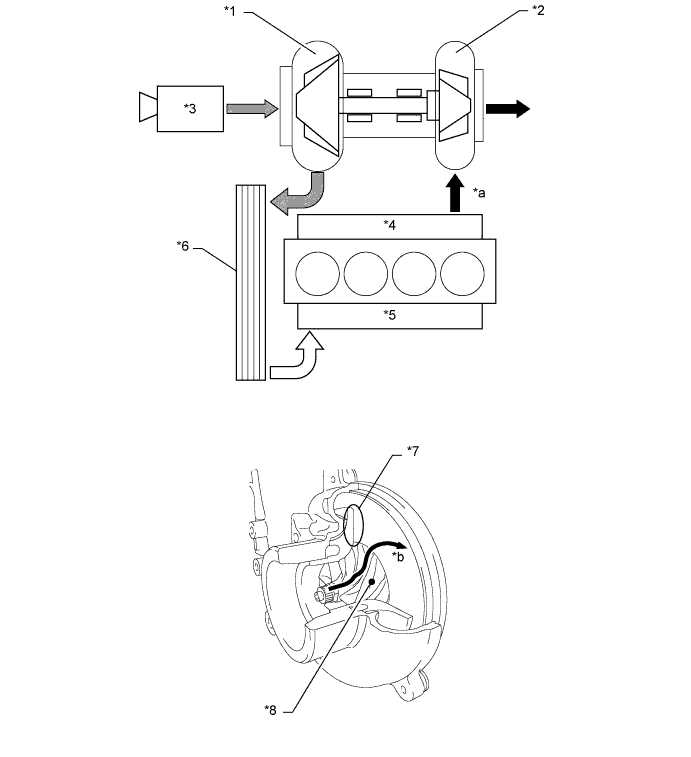
Text in Illustration *1
Compressor *2
Turbine *3
Air Cleaner *4
Exhaust Manifold *5
Intake Manifold *6
Intercooler *7
Diffuser *8
Compressor *a
See HINT below *b
Intake air flow Tech Tips
-
*a: If sufficient exhaust gas energy is not available, the turbocharger cannot generate the required boost pressure even when the turbocharger does not have a malfunction.
-
Considering the fact that the turbocharger is driven by exhaust gas energy, if sufficient exhaust gas is not available due to abnormal injection volume, etc., the required boost pressure will not be available even when the turbocharger does not have a malfunction. Therefore, when boost pressure is abnormally low, checking all the related components using the correct troubleshooting procedure is necessary for simple and effective repair.
-
-
Boost Pressure Control:
When the boost pressure (turbocharged air pressure) exceeds the prescribed air pressure, the flow of exhaust gas bypasses the turbine, controlling turbine wheel revolutions and boost pressure. This bypass valve which controls the quantity of exhaust gas flowing to the turbine is called the waste gate valve. When the boost pressure exceeds the prescribed pressure, the actuator operates, the waste gate valve opens and part of the exhaust gas bypasses the turbine. This causes a drop in the turbine revolution rate and controls the boost pressure within the prescribed limits.
Tech Tips
If the waste gate valve becomes stuck open, the necessary boost pressure will not be available. If the waste gate valve becomes stuck closed, overboost will occur.
-
Mechanical Construction of Turbocharger:
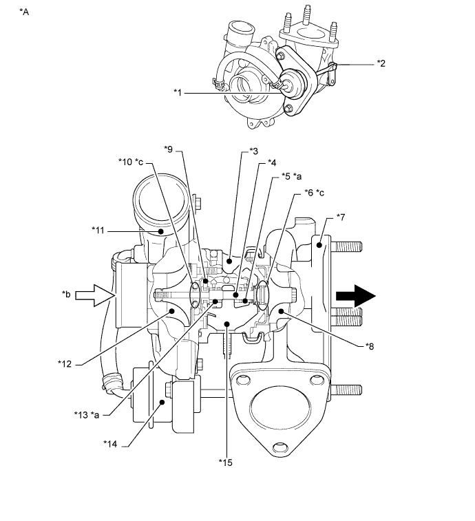
Text in Illustration 
Exhaust Gas Flow 
Intake Air Flow *A
Waste Gate Type Turbocharger - - *1
Waste Gate Actuator *2
Actuating Rod *3
Bearing Housing *4
Turbine Shaft *5
Radial Bearing *6
Turbine Side Seal Ring *7
Turbine Housing *8
Turbine Wheel *9
Thrust Bearing *10
Compressor Side Seal Ring *11
Compressor Housing *12
Compressor Impeller *13
Radial Bearing *14
Waste Gate Actuator *15
Oil Drain - - *a
See HINT below *b
See HINT below *c
See HINT below - - Tech Tips
-
Above illustration is an example.
-
*a: The clearances of the radial bearing and thrust bearing are on the order of 100 μm, and for the accurate measurement of these clearances, an accurate process and accurate tools are essential.
-
*b: A certain amount of oil mist from PCV gas is contained in the intake air. Therefore, a certain amount of oil at the inlet of the compressor is normal, and is not an oil leak.
-
*c: The seal rings are C-shaped rings just like piston rings, and have a gap. Therefore, complete sealing is impossible by the seal rings alone. The oil is sealed in with the aid of the boost pressure in the compressor housing, and the exhaust gas pressure in the turbine housing. These pressures prevent oil from exiting the bearing housing through the gap of the seal rings. Therefore, if the turbine shaft is inclined from the horizontal, oil may flow out through the gap of a seal ring. This should not be interpreted as an oil leak due to seal ring failure.
-
-