ТУРБОНАГНЕТАТЕЛЬ УСТАНОВКА
-
INSTALL STUD BOLT
Note
If a stud bolt is deformed or its threads are damaged, replace it.
-
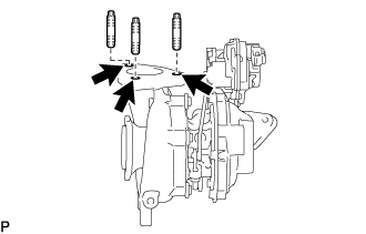
Using an E10 "TORX" socket wrench, install the 3 stud bolts at the positions shown in the illustration.
- Torque:
- 15 N*m { 150 kgf*cm, 11 ft.*lbf }
-
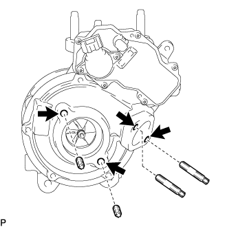
Using an E8 "TORX" socket wrench, install the 4 stud bolts at the positions shown in the illustration.
- Torque:
- 10 N*m { 102 kgf*cm, 7 ft.*lbf }
-
Using an E5 "TORX" socket wrench, install the 4 stud bolts at the positions shown in the illustration.
- Torque:
- 5.5 N*m { 56 kgf*cm, 49 in.*lbf }
-
-
INSTALL COMPRESSOR OUTLET ELBOW
-
Install a new gasket and the compressor outlet elbow with the 2 nuts.
- Torque:
- 21 N*m { 214 kgf*cm, 15 ft.*lbf }
-
-
INSTALL COMPRESSOR INLET ELBOW
-
Install a new gasket.
-
Install the compressor inlet elbow to the turbocharger sub-assembly with the 2 nuts.
- Torque:
- 21 N*m { 214 kgf*cm, 15 ft.*lbf }
-
-
INSTALL NO. 1 TURBO WATER PIPE SUB-ASSEMBLY
-
Install a new gasket.
-
Temporarily install the No. 1 turbo water pipe sub-assembly with the bolt and 2 nuts.
-
Tighten the bolt and 2 nuts.
- Torque:
- 13 N*m { 133 kgf*cm, 10 ft.*lbf }
-
Connect the No. 1 turbo water hose and No. 2 turbo water hose to the No. 1 turbo water pipe sub-assembly, and slide the 2 hose clips to secure the hoses.
-
-
TEMPORARILY INSTALL TURBO OIL INLET PIPE SUB-ASSEMBLY
-
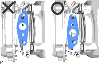
Text in Illustration *a NG *b OK Install a new gasket as shown in the illustration.
Note
Do not install the gasket upside down.
-
Temporarily install the turbo oil inlet pipe sub-assembly with the 2 nuts.
-
-
TEMPORARILY INSTALL EXHAUST MANIFOLD WITH TURBOCHARGER SUB-ASSEMBLY
-
Install 2 new gaskets to the exhaust manifold and turbocharger sub-assembly.
-
Temporarily install the exhaust manifold to turbocharger sub-assembly with 3 new nuts.
-
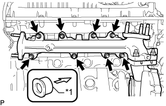
Text in Illustration *1 Collar 
Engine Side Temporarily install the exhaust manifold with turbocharger sub-assembly, 8 collars and 8 plate washers to the cylinder head sub-assembly with 8 new nuts.
Note
Make sure that the side of the collar with the smaller diameter faces the exhaust manifold.
-
Install a new gasket on the union bolt side to turbo oil inlet pipe sub-assembly.
-
Temporarily install the union bolt.
-
-
INSTALL TURBO OIL OUTLET PIPE
-
Install a new gasket to the turbo oil outlet pipe.
Note
The claws of the gasket must face the turbo oil outlet pipe.
-
Install the turbo oil outlet pipe with the 2 bolts.
- Torque:
- 12 N*m { 122 kgf*cm, 9 ft.*lbf }
-
Connect the turbo oil outlet hose to the turbo oil outlet pipe, turbo oil inlet pipe and slide the 2 hose clips to secure the hoses.
-
-
TEMPORARILY INSTALL TURBOCHARGER STAY
-
Temporarily install the turbocharger stay to the turbocharger sub-assembly with the 3 bolts and nut.
-
-
TIGHTEN EXHAUST MANIFOLD WITH TURBOCHARGER SUB-ASSEMBLY
-
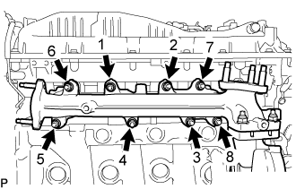
Tighten the exhaust manifold with turbocharger sub-assembly to the cylinder head sub-assembly with the 8 nuts.
- Torque:
- 40 N*m { 408 kgf*cm, 30 ft.*lbf }
Tech Tips
Tighten the nuts in the order shown in the illustration.
-
Tighten the turbocharger sub-assembly to the exhaust manifold with the 3 nuts.
- Torque:
- 73 N*m { 744 kgf*cm, 54 ft.*lbf }
-
Tighten the 2 nuts and union bolt of the turbo oil inlet pipe sub-assembly.
- Torque:
- for nut
- 13 N*m { 133 kgf*cm, 10 ft.*lbf }
- for union bolt
- 36 N*m { 367 kgf*cm, 27 ft.*lbf }
Note
If the connecting part of the union bolt gasket is cracked, remove the connecting part.
-
-
TIGHTEN TURBOCHARGER STAY
-
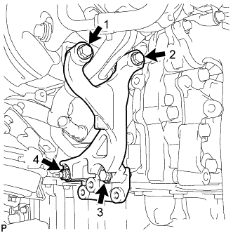
Tighten the 3 bolts and nut of the turbocharger stay in the order shown in the illustration.
- Torque:
- 24 N*m { 245 kgf*cm, 18 ft.*lbf }
-
-
INSTALL OIL COOLER TUBE BRACKET AND WIRE HARNESS CLAMP BRACKET
-
Connect the oil cooler tube bracket with the bolt.
- Torque:
- 5.5 N*m { 56 kgf*cm, 47 in.*lbf }
-
-
INSTALL NO. 1 EGR PIPE SUB-ASSEMBLY
-
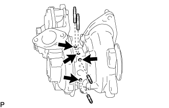
Using an E8 "TORX" socket wrench, install 2 new stud bolts to the exhaust manifold.
- Torque:
- 10 N*m { 102 kgf*cm, 7 ft.*lbf }
-
Install 2 new gaskets and the No. 1 EGR pipe sub-assembly to the exhaust manifold, electric EGR control valve assembly and No. 1 vacuum transmitting pipe sub-assembly with the bolt and 4 new nuts.
- Torque:
- for bolt
- 10 N*m { 102 kgf*cm, 7 ft.*lbf }
- for nut
- 29 N*m { 296 kgf*cm, 21 ft.*lbf }
-
-
CONNECT TURBO WATER HOSE
Note
The turbocharger sub-assembly may be damaged if the No. 1 turbo water hose and No. 2 turbo water hose are connected to the wrong locations.
-
Connect the No. 2 turbo water hose to the water outlet sub-assembly, and slide the 2 hose clips to secure the hoses.
-
Connect the No. 1 turbo water hose to the engine water pump assembly, and slide the 2 hose clips to secure the hoses.
-
-
INSTALL NO. 2 WATER BY-PASS PIPE SUB-ASSEMBLY
-
Install the No. 2 water by-pass pipe sub-assembly with the 2 bolts.
- Torque:
- 10 N*m { 102 kgf*cm, 7 ft.*lbf }
-
Connect the No. 2 water by-pass hose and No. 3 water by-pass hose to the water outlet sub-assembly and engine oil cooler assembly and slide the 2 hose clips to secure the hoses.
-
-
INSTALL PCV HOSE CLAMP
-
Install the PCV hose clamp with the 2 bolts.
- Torque:
- 10 N*m { 102 kgf*cm, 7 ft.*lbf }
-
Connect the 2 connectors and attach the wire harness clamp.
-
-
INSTALL PCV HOSE
-
Attach the clamp, install the PCV hose and slide the 2 hose clips to secure the hoses.
-
Slide the 2 hose clips to secure the hoses.
-
-
INSTALL EXHAUST MANIFOLD CONVERTER SUB-ASSEMBLY
-
CONNECT CABLE TO NEGATIVE BATTERY TERMINAL
Note
When disconnecting the cable, some systems need to be initialized after the cable is reconnected Click here.
-
ADD ENGINE OIL
-
Add new engine oil and install the oil filler cap sub-assembly.
Oil Grade Oil Grade Oil Viscosity (SAE) ACEA C2
(Using engine oil other than ACEA C2 may damage the catalytic converter)
- 0W-30 Standard Capacity Item Specified Condition Drain and refill without oil filter sub-assembly change 5.5 liters (5.8 US qts, 4.8 Imp. qts) Drain and refill with oil filter sub-assembly change 6.1 liters (6.4 US qts, 5.4 Imp. qts) Dry fill 7.0 liters (7.4 US qts, 6.2 Imp. qts)
-
-
ADD ENGINE COOLANT
-
Надежно затяните сливные пробки.
-
Залейте в расширительный бачок системы охлаждения охлаждающую жидкость двигателя до верха горловины.
Номинальный объем 13,9 л (14,6 кварты США, 12,2 английской кварты) Note
Не доливайте простую воду вместо охлаждающей жидкости двигателя.
Tech Tips
-
Использование неподходящей охлаждающей жидкости может привести к повреждению системы охлаждения двигателя.
-
Разрешается использовать только охлаждающую жидкость "TOYOTA Super Long Life Coolant (SLLC)" или аналогичную высококачественную охлаждающую жидкость на основе этиленгликоля (не на силикатной, аминовой, нитритной или борнокислой основе), изготовленную по гибридной технологии органических кислот с длительным сроком годности (охлаждающая жидкость, изготовленная по гибридной технологии органических кислот с длительным сроком годности, состоит из низкофосфатных соединений и органических кислот).
-
-
Ослабьте прокачной штуцер выпускного патрубка охлаждающей жидкости в сборе.
-
После удаления воздуха и слива охлаждающей жидкости двигателя надежно затяните прокачной штуцер.
- Torque:
- 8,0 Н*м { 82 кгс*см, 71 фунт-сила-дюйм }
-
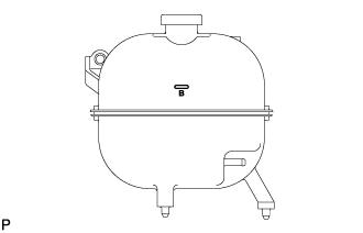
Долейте охлаждающую жидкость двигателя в расширительный бачок системы охлаждения до отметки B и установите пробку радиатора.
-
Прогревайте двигатель, пока не откроется термостат.
-
Когда термостат откроется, несколько минут прокачивайте охлаждающую жидкость двигателя.
Tech Tips
Время открывания термостата можно проверить, сжав шланг радиатора № 3 рукой и определив, когда охлаждающая жидкость начинает поступать в шланг.
-
-
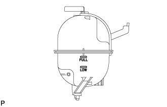
После охлаждения двигателя убедитесь, что уровень охлаждающей жидкости двигателя находится между отметками "LOW" и "FULL".
-
-
INSPECT FOR OIL LEAK
-
Start the engine. Make sure that there are no oil leaks from the areas that were worked on.
-
-
INSPECT ENGINE OIL LEVEL
-
Warm up the engine, and then stop the engine and wait 5 minutes.
-
Check that the engine oil level is between the engine oil level dipstick low level mark and full level mark.
If the engine oil level is low, check for leaks and add engine oil to the full level mark.
Note
Do not fill engine oil above the full level mark.
Tech Tips
A certain amount of engine oil will be consumed while driving. In the following situations, oil consumption may increase, and engine oil may need to be refilled in between oil maintenance intervals.
-
When the engine is new, for example directly after purchasing the vehicle or after replacing the engine.
-
If low quality oil or oil of an inappropriate viscosity is used.
-
When driving at a high engine speed or with a heavy load, when towing, or when driving while accelerating or decelerating frequently.
-
When idling for a long time, or when driving frequently through heavy traffic.
When judging the amount of oil consumption, keep in mind that the oil may have become diluted, making it difficult to judge the true level accurately.
-
-
-
INSPECT FOR COOLANT LEAK
CAUTION:
Не снимайте пробку радиатора, пока двигатель и радиатор не остынут. Выброс горячей охлаждающей жидкости и пара под давлением может стать причиной серьезных ожогов.
-
Заполните радиатор охлаждающей жидкостью и подсоедините к радиатору приспособление для опрессовки системы охлаждения и проверки пробки радиатора.
-
Прогрейте двигатель.
-
С помощью приспособления для опрессовки системы охлаждения и проверки пробки радиатора увеличьте давление в радиаторе до 137 кПа (1,4 кгс/см2, 19,9 фунтов на кв. дюйм) и убедитесь, что давление не падает.
Tech Tips
Если давление снижается, проверьте на наличие утечек шланги, радиатор в сборе и насос системы охлаждения двигателя в сборе. При отсутствии внешних утечек проверьте сердцевину отопителя, блок цилиндров в сборе и головку блока цилиндров в сборе.
-
-
INSPECT FOR EXHAUST GAS LEAK
-
If gas is leaking, tighten the areas necessary to stop the leak. Replace damaged parts as necessary.
-