ВПУСКНОЙ КОЛЛЕКТОР УСТАНОВКА

Note
-
When replacing the parts in the following chart (A), replace the No. 1 injection pipe sub-assembly, No. 2 injection pipe sub-assembly and/or fuel inlet pipe sub-assembly with new ones.
Replaced Parts (A) Pipes Requiring New Replacement
-
Injector assembly (including shuffling the injector assemblies between the cylinders)
-
Common rail assembly
-
Injection pipe sub-assembly or supply pump assembly
-
No. 1 injection pipe sub-assembly
-
No. 2 injection pipe sub-assembly
Common rail assembly Fuel inlet pipe sub-assembly
-
Injection pipe sub-assembly or supply pump assembly
-
Cylinder block sub-assembly
-
Cylinder head sub-assembly
-
Cylinder head gasket
-
Timing chain case assembly or belt cover sub-assembly
-
No. 1 injection pipe sub-assembly
-
No. 2 injection pipe sub-assembly
-
Fuel inlet pipe sub-assembly
-
-
After removing the No. 1 injection pipe sub-assembly, No. 2 injection pipe sub-assembly and/or fuel inlet pipe sub-assembly, clean them with a brush and compressed air.
-
INSTALL INTAKE MANIFOLD
-
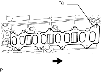
Install a new gasket to the cylinder head sub-assembly.
Tech Tips
Install the gasket with the protrusion facing the rear side of the vehicle as shown in the illustration.
Text in Illustration *a Protrusion 
Rear side -
Temporarily install the intake manifold with the 7 bolts and 2 nuts.
-
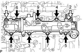
Tighten the 7 bolts and 2 nuts in the order shown in the illustration.
- Torque:
- 23 N*m { 235 kgf*cm, 17 ft.*lbf }
Text in Illustration Bolt 
Nut -
Connect the wire harness bracket with the bolt.
- Torque:
- 13 N*m { 130 kgf*cm, 9 ft.*lbf }
-
-
INSTALL VACUUM CONTROL VALVE SET
-
Install the vacuum control valve set to the intake manifold with the bolt.
- Torque:
- 10 N*m { 102 kgf*cm, 7 ft.*lbf }
-
Connect the 2 vacuum hoses to the swirl control valve actuator and vacuum transmitting pipe sub-assembly.
-
Connect the wire harness clamp and vacuum control valve set connector.
-
-
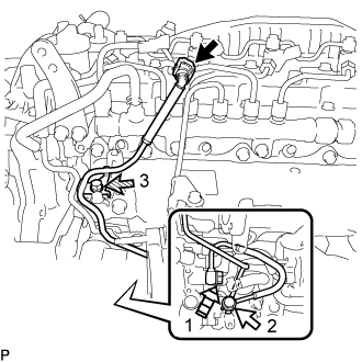
INSTALL NO. 2 NOZZLE LEAKAGE PIPE ASSEMBLY
-
Install the No. 2 nozzle leakage pipe assembly with the 2 bolts.
- Torque:
- 10 N*m { 102 kgf*cm, 7 ft.*lbf }
-
Connect the No. 6 fuel hose to the No. 3 nozzle leakage pipe assembly, and slide the clamp to secure the hose.
-
Install the No. 4 fuel hose to the No. 2 nozzle leakage pipe assembly, common rail assembly and slide the 2 clamps to secure the hoses.
-
Install the No. 5 fuel hose to the No. 2 nozzle leakage pipe assembly, No. 1 nozzle leakage pipe assembly and slide the 2clamps to secure the hoses.
-
-
INSTALL FUEL INLET PIPE SUB-ASSEMBLY
Note
When replacing the fuel supply pump assembly, it is necessary to replace the fuel inlet pipe sub-assembly, No. 1 injection pipe clamp and No. 2 injection pipe clamp with a new one. Keep the fuel inlet pipe sub-assembly free of foreign matter.
-
Temporarily install the fuel inlet pipe sub-assembly.
-
Install a new No. 1 injection pipe clamp and No. 2 injection pipe clamp with the 2 bolts.
- Torque:
- 10 N*m { 102 kgf*cm, 7 ft.*lbf }
-
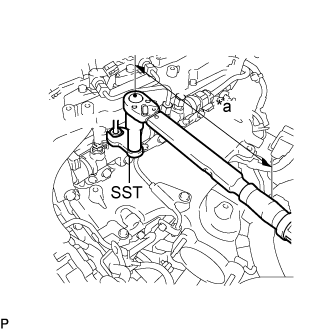
Text in Illustration *a Torque Wrench Fulcrum Length Using SST, tighten the fuel inlet pipe sub-assembly union nut on the common rail side sub-assembly.
- SST
- 09245-11010
- Torque:
- Specified tightening torque
- 40 N*m { 408 kgf*cm, 30 ft.*lbf }
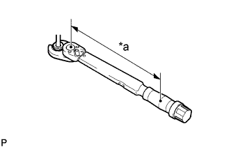
Tech Tips
-
Calculate the torque wrench reading when changing the fulcrum length of the torque wrench.
-
When using a union nut wrench (fulcrum length of 50 mm (1.97 in.)) + torque wrench (fulcrum length of 180 mm (7.09 in.)): 31 N*m (316 kgf*cm, 23 ft.*lbf)
-
Text in Illustration *a Torque Wrench Fulcrum Length Using a 19 mm union nut wrench, tighten the fuel inlet pipe sub-assembly union nut on the fuel supply pump assembly side.
- Torque:
- Specified tightening torque
- 48 N*m { 489 kgf*cm, 35 ft.*lbf }
Tech Tips
-
Calculate the torque wrench reading when changing the fulcrum length of the torque wrench.
-
When using a union nut wrench (fulcrum length of 30 mm (1.18 in.)) + torque wrench (fulcrum length of 180 mm (7.09 in.)): 41 N*m (418 kgf*cm, 30 ft.*lbf)
-
-
INSTALL NO. 4 FUEL PIPE SUB-ASSEMBLY
-
Temporarily install the No. 4 fuel pipe sub-assembly and 2 new gaskets with the 2 union bolts and bolt.
-
Text in Illustration Union Bolt 
Bolt 
Supply Pump Hollow Screw Tighten the union bolt and bolt in the order shown in the illustration.
- Torque:
- union bolt
- 42 N*m { 428 kgf*cm, 31 ft.*lbf }
- bolt
- 10 N*m { 102 kgf*cm, 7 ft.*lbf }
-
Tighten the supply pump hollow screw in the order shown in the illustration.
- Torque:
- 42 N*m { 428 kgf*cm, 31 ft.*lbf }
-
Connect the No. 4 fuel pipe sub-assembly to the No. 1 fuel pipe Click here.
-
-
INSTALL MANIFOLD STAY
-
Install the manifold stay with the 2 bolts.
- Torque:
- 21 N*m { 214 kgf*cm, 15 ft.*lbf }
-
Install the wiring harness clamp bracket with the bolt.
- Torque:
- 13 N*m { 128 kgf*cm, 9 ft.*lbf }
-
-
INSTALL WIRING HARNESS CLAMP BRACKET
-
Install the wiring harness clamp bracket with the bolt.
- Torque:
- 10 N*m { 102 kgf*cm, 7 ft.*lbf }
-
Attach the 2 wire harness clamps.
-
Connect the diesel throttle body assembly connector and pre-stroke control valve connector.
-
-
INSTALL NO. 2 FUEL PIPE
-
Connect the No. 2 fuel pipe with the bolt.
- Torque:
- 10 N*m { 102 kgf*cm, 7 ft.*lbf }
-
-
REMOVE ENGINE OIL LEVEL DIPSTICK GUIDE
-
Apply a light coat of engine oil to a new O-ring and new grommet.
-
Install the O-ring and grommet to the engine oil level dipstick guide.
-
Install the engine oil level dipstick guide with the bolt.
- Torque:
- 10 N*m { 102 kgf*cm, 7 ft.*lbf }
-
Connect the vacuum hose to the intake manifold, and slide the clip to secure the hose.
-
Install the engine oil level dipstick.
-
-
INSTALL EGR COOLER ASSEMBLY
-
CONNECT CABLE TO NEGATIVE BATTERY TERMINAL
Note
When disconnecting the cable, some systems need to be initialized after the cable is reconnected Click here.
-
ADD ENGINE COOLANT
-
Надежно затяните сливные пробки.
-
Залейте в расширительный бачок системы охлаждения охлаждающую жидкость двигателя до верха горловины.
Номинальный объем 13,9 л (14,6 кварты США, 12,2 английской кварты) Note
Не доливайте простую воду вместо охлаждающей жидкости двигателя.
Tech Tips
-
Использование неподходящей охлаждающей жидкости может привести к повреждению системы охлаждения двигателя.
-
Разрешается использовать только охлаждающую жидкость "TOYOTA Super Long Life Coolant (SLLC)" или аналогичную высококачественную охлаждающую жидкость на основе этиленгликоля (не на силикатной, аминовой, нитритной или борнокислой основе), изготовленную по гибридной технологии органических кислот с длительным сроком годности (охлаждающая жидкость, изготовленная по гибридной технологии органических кислот с длительным сроком годности, состоит из низкофосфатных соединений и органических кислот).
-
-
Ослабьте прокачной штуцер выпускного патрубка охлаждающей жидкости в сборе.
-
После удаления воздуха и слива охлаждающей жидкости двигателя надежно затяните прокачной штуцер.
- Torque:
- 8,0 Н*м { 82 кгс*см, 71 фунт-сила-дюйм }
-
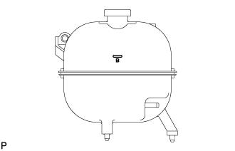
Долейте охлаждающую жидкость двигателя в расширительный бачок системы охлаждения до отметки B и установите пробку радиатора.
-
Прогревайте двигатель, пока не откроется термостат.
-
Когда термостат откроется, несколько минут прокачивайте охлаждающую жидкость двигателя.
Tech Tips
Время открывания термостата можно проверить, сжав шланг радиатора № 3 рукой и определив, когда охлаждающая жидкость начинает поступать в шланг.
-
-
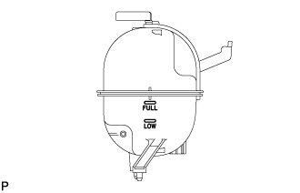
После охлаждения двигателя убедитесь, что уровень охлаждающей жидкости двигателя находится между отметками "LOW" и "FULL".
-
-
BLEED AIR FROM FUEL SYSTEM
-
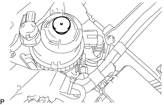
Using the hand pump mounted on the fuel filter cap, bleed air from the fuel system. Continue pumping until the pump resistance increases.
Note
-
The maximum hand pump pumping speed is 2 strokes per second.
-
The hand pump must be pushed with a full stroke during pumping.
-
When the fuel pressure at the supply pump inlet port reaches a saturated pressure, the hand pump resistance increases.
-
If pumping is interrupted during the air bleeding process, fuel in the fuel line may return to the fuel tank. Continue pumping until the hand pump resistance increases.
-
If the hand pump resistance does not increase despite consecutively pumping 200 times or more, there may be a fuel leak between the fuel tank and fuel filter, the hand pump may be malfunctioning, or the vehicle may have run out of fuel.
-
If air bleeding using the hand pump is incomplete, the common rail pressure does not rise to the pressure range necessary for normal use and the engine cannot be started.
-
-
Check if the engine starts.
Note
-
Even if air bleeding using the hand pump has been completed, the starter may need to be cranked for 10 seconds or more to start the engine.
-
Do not crank the engine continuously for more than 20 seconds. The battery may be discharged.
-
Use a fully-charged battery.
-
When the engine can be started, proceed to the next step.
-
If the engine cannot be started, bleed air again using the hand pump until the hand pump resistance increases (refer to the procedures above). Then start the engine.
-
-
Turn the ignition switch off.
-
Connect the GTS to the DLC3.
-
Turn the ignition switch to ON and turn the GTS on.
-
Clear the DTCs Click here.
-
Start the engine.*1
-
Enter the following menus: Powertrain / Engine and ECT / Active Test / Test the Fuel Leak.*2
-
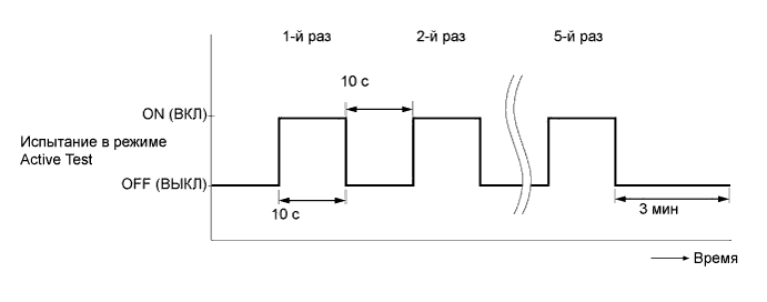
Perform the following test 5 times with on/off intervals of 10 seconds: Active Test / Test the Fuel Leak.*3
-
Allow the engine to idle for 3 minutes or more after performing the Active Test for the 5th time.
Tech Tips
When the Active Test "Test the Fuel Leak" is used to change the pump control mode, the actual fuel pressure inside the common rail drops below the target fuel pressure when the Active Test is off, but this is normal and does not indicate a pump malfunction.
-
Enter the following menus: Powertrain / Engine and ECT /Trouble Codes.
-
Read Current DTCs.
-
Clear the DTCs Click here.
Tech Tips
It is necessary to clear the DTCs as DTC P1604 or P1605 may be stored when air is bled from the fuel system after replacing or repairing fuel system parts.
-
Repeat steps *1 to *3.
-
Enter the following menus: Powertrain / Engine and ECT / Trouble Codes.
-
Read Current DTCs.
OK No DTCs are output.
-