- Click here
INSTALL AIR SWITCHING VALVE ASSEMBLY
-
Install the air switching valve assembly with 2 new nuts.
26 N*m 265 kgf*cm 19 ft.*lbf -
Connect the air switching valve connector.
-
- Click here
INSTALL NO. 4 INTAKE PIPE
-
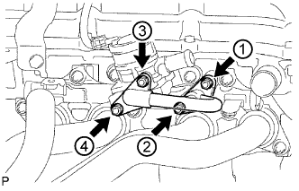
Install 2 new gaskets and the No. 4 intake pipe with 4 new nuts in the order shown in the illustration. Tighten the nuts labeled 1 and 3 to the torque specification again.
26 N*m 265 kgf*cm 19 ft.*lbf -
Check that the nuts are tightened to the torque specification.
Note:Tightening the nuts only once is not enough to tighten them to the torque specification.
-
- Click here
INSTALL NO. 1 EXHAUST MANIFOLD HEAT INSULATOR
-
Install the No. 1 exhaust manifold heat insulator with the 4 bolts.
12 N*m 122 kgf*cm 9 ft.*lbf
-
- Click here
INSTALL AIR PUMP INLET PIPE
-
Install the air pump inlet pipe with the 2 bolts.
18 N*m 184 kgf*cm 13 ft.*lbf -
Connect the No. 5 air hose, and slide the clamp to secure the hose.
-
Connect the No. 6 air hose, and slide the clamp to secure the hose.
-
- Click here
INSTALL BATTERY SERVICE HOLE COVER
- Click here
INSTALL ENGINE SERVICE HOLE SUB COVER SUB-ASSEMBLY
-
Установите крышку технологического отверстия двигателя и закрепите 5 болтами.
13 Н*м 133 кгс*см 10 фунт-сила-футов
-
- Click here
INSTALL FRONT DOOR SCUFF PLATE RH
- Click here
INSTALL FRONT SEAT ASSEMBLY RH
- Click here
CONNECT CABLE TO NEGATIVE BATTERY TERMINAL
Note:When disconnecting the cable, some systems need to be initialized after the cable is reconnected (Click here).
- Click here
PERFORM INITIALIZATION