НАСОС ПОДАЧИ МОЧЕВИНЫ СНЯТИЕ

-
REMOVE UREA TANK SUB-ASSEMBLY
-
REMOVE UREA PUMP
-
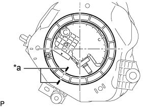
Text in Illustration *a Co-rotation Prevention Check Mark Apply a co-rotation prevention check mark to the urea pump from the urea tank sub-assembly.
Note
-
The urea tank sub-assembly cutout is attached to protrusion on the urea tube with heater assembly.
-
If the urea pump and urea tank sub-assembly are not firmly attached and the urea pump gauge retainer is rotated, the urea pump will co-rotate and result in urea pump being damaged.
-
Make sure to apply co-rotation prevention check mark to prevent the urea pump from co-rotating.
-
-
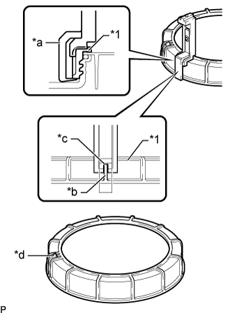
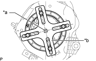
Text in Illustration *1 Urea Pump gauge Retainer *a SST (Claw Set) *b Rib *c Cutout *d SST (Claw Set) Incorrect Installation Point (Rotational Start Point Mark of Urea Pump Gauge Retainer) Set 4 SSTs (claw sets) to the urea pump gauge retainer and temporarily install.
- SST
- 09808-14031 ( 09808-01080, 09808-01090, 09808-01100 )
Note
-
Align the cutout of SST (claw set) to the rib of the urea pump gauge retainer.
-
Do not place SST on the rotational start paint mark of the urea pump gauge retainer, otherwise SST (claw set) cannot be set correctly.
-
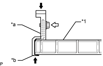
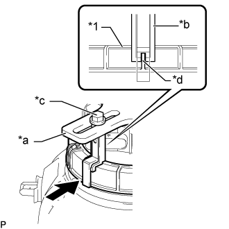
Text in Illustration *1 Urea Pump Gauge Retainer *a SST (Claw Set) *b Press 
Pinch 
SST (Bolt) While firmly pressing the claw of SST into rib of the urea pump gauge retainer, tighten the bolt.
-
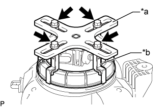
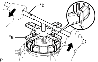
Text in Illustration *a SST (Plate) *b SST (Claw Set) SST (Bolt) Temporarily install SST (plate) to SST (claw set) with 4 SSTs (bolts).
-
Text in Illustration *a Center of Urea Pump Gauge Retainer *b SST (Plate) Adjust the position of SST (plate) so that the setting hole of SST (handle) aligns with the center of the urea pump gauge retainer.
-
Text in Illustration *1 Urea Pump Gauge Retainer *a SST (Plate) *b SST (Claw Set) *c SST (Bolt) *d Rib Press While firmly pressing SST (claw set) into rib of the urea pump gauge retainer, tighten SST (bolt).
-
Text in Illustration *a SST (Plate) *b SST (Handle) *c SST (Claw Set) Loosen Install SST (handle) to SST (plate).
- SST
- 09808-14031 ( 09808-01010, 09808-01020 )
-
Slowly loosen the urea pump gauge retainer by approximately 90°.
Note
-
Do not use any tools other than SST, such as screwdriver, etc.
-
Do not excessive force when pressing down on SST, as urea tube with heater assembly will place excessive force on the urea pump gauge retainer and be difficult to remove, and parts may be damaged.
-
Do not use an impact wrench or turn SST handle with excessive force, as parts may be damaged.
-
-
While on person slowly loosens the urea pump gauge retainer, have another person press down the rising urea pump, securely attach the protrusion of the urea pump to the groove of the urea tank sub-assembly, and then remove the urea pump gauge retainer while making sure that the urea pump is properly aligned.
Note
-
If the urea pump gauge retainer is turned while the urea pump and urea tank sub-assembly are not correctly aligned, urea pump will move with the urea pump gauge retainer, and the urea pump and urea tank sub-assembly may both be damaged.
-
Do not rotate the urea pump gauge retainer when the co-rotation prevention check mark is out of place.
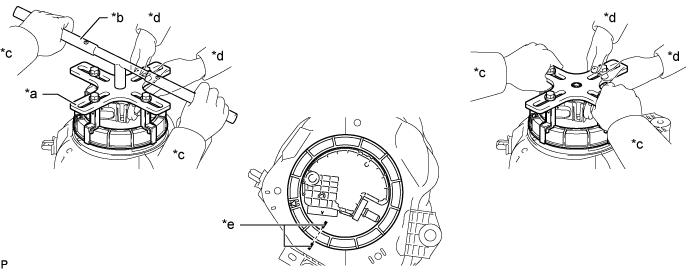
Text in Illustration *a SST (Plate) *b SST (Handle) *c Person in Charge of Loosening *d Person in Charge of Supporting *e Co-rotation Prevention Check Mark - - -
-
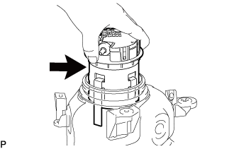
Remove the urea pump from the urea tank sub-assembly.
-
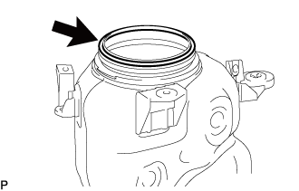
Remove the gasket from the urea tank sub-assembly.
-