КЛАПАН РОГ СНЯТИЕ
-
DRAIN ENGINE COOLANT
CAUTION:
Не снимайте пробку радиатора, пока двигатель и радиатор не остынут. Выброс горячей охлаждающей жидкости и пара под давлением может стать причиной серьезных ожогов.
-
Подсоедините шланг с внутренним диаметром 9 мм (0,354 дюйма) к сливному крану радиатора.
-
Ослабьте пробку сливного крана радиатора.
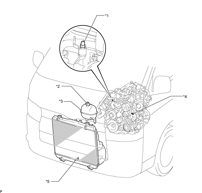
Обозначения на рисунке *1 Прокачной штуцер *2 Пробка радиатора *3 Расширительный бачок системы охлаждения в сборе *4 Пробка сливного крана блока цилиндров *5 Пробка сливного крана радиатора - - -
Снимите пробку радиатора.
-
Ослабьте пробку сливного крана блока цилиндров и слейте охлаждающую жидкость двигателя.
-
Затяните пробку сливного крана радиатора.
-
Затяните пробку сливного крана блока цилиндров.
- Torque:
- 13 Н*м { 130 кгс*см, 9 фунт-сила-футов }
-
Отсоедините шланг от сливного крана радиатора.
-
-
REMOVE SEAT TRACK COVER LH
-
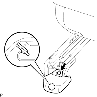
С помощью съемника фиксаторов освободите фиксатор.
-
Расцепите захват и снимите щиток направляющей левого сиденья.
-
-
REMOVE FRONT SEAT ASSEMBLY RH
-
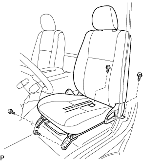
Выдвиньте переднее сиденье в сборе до упора вперед.
-
Выверните 2 болта с задней стороны сиденья.
-
Сдвиньте переднее сиденье в сборе в крайнее заднее положение.
-
Выверните 2 болта с передней стороны сиденья.
-
Сдвиньте переднее сиденье в сборе к середине направляющей сиденья. Установите спинку сиденья в вертикальное положение.
-
Отсоедините разъем замка ремня безопасности переднего сиденья.
-
Снимите переднее сиденье в сборе.
-
-
REMOVE FRONT DOOR SCUFF PLATE RH
-
REMOVE ENGINE SERVICE HOLE SUB COVER SUB-ASSEMBLY
-
Отогните напольный коврик.
-
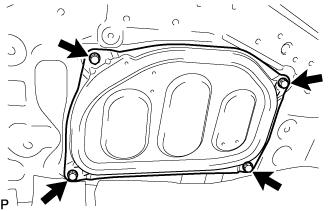
Выверните 5 болтов и снимите вспомогательную крышку технологического отверстия двигателя.
-
-
REMOVE TRANSMISSION SERVICE HOLE COVER SUB-ASSEMBLY
-
Снимите 2 крышки крепления ремня безопасности.
-
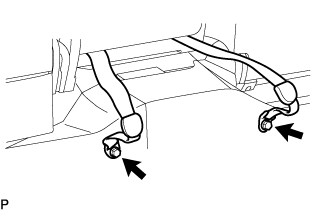
Выверните 2 болта и отсоедините правый ремень безопасности центрального переднего сиденья в сборе и поясной ремень безопасности переднего центрального сиденья в сборе.
-
Освободите фиксаторы и отогните коврик.
-
Выверните 4 болта и снимите крышку технологического отверстия трансмиссии с кузова.
-
-
REMOVE DIESEL THROTTLE BODY ASSEMBLY
-
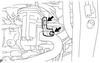
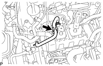
REMOVE NO. 16 WATER BY-PASS HOSE
-
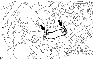
Slide the 2 clamps and remove the No. 16 water by-pass hose from the No. 1 EGR cooler and No. 2 water by-pass pipe.
-
-
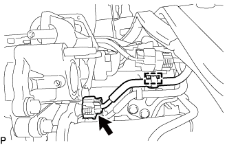
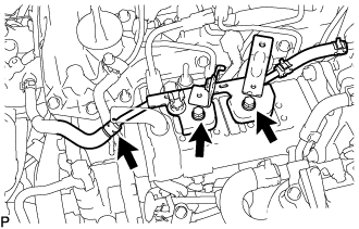
REMOVE DIESEL TURBO PRESSURE SENSOR
-
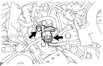
Disconnect the connector from the diesel turbo pressure sensor.
-
Remove the bolt and diesel turbo pressure sensor from the No. 3 water by-pass pipe sub-assembly.
-
-
DISCONNECT ENGINE WIRE
-
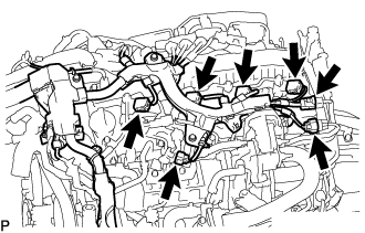
Detach the 2 clamps and disconnect the 2 connectors from the turbocharger sub-assembly.
-
Disconnect the connector from the camshaft position sensor.
-
Detach the clamp and disconnect the connector from the differential pressure sensor.
-
Disconnect the 3 connectors from the exhaust gas temperature sensors.
-
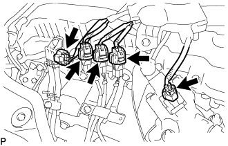
Disconnect the connector from the exhaust fuel addition injector assembly.
-
Disconnect the 4 connectors from the 4 injector assemblies.
-
Disconnect the electric EGR control valve assembly.
-
Disconnect the connector from the glow plug connector.
-
Disconnect the connector from the sensor wire of common rail assembly.
-
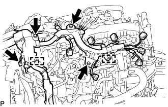
Detach the 2 clamps and remove the 4 bolts.
-
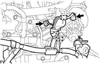
Disconnect the connector from the swirl control valve.
-
Disconnect the connector from the vacuum control valve set.
-
Detach the 2 clamps and disconnect the engine wire from the engine assembly.
-
-
REMOVE EGR VALVE BRACKET
-
Remove the bolt, nut and EGR valve bracket from the electric EGR control valve assembly and intake manifold.
-
-
REMOVE NO. 2 EGR PIPE
-
Remove the bolt, 4 nuts and No. 2 EGR pipe from the electric EGR control valve assembly and intake manifold.
-
Remove the 2 gaskets.
-
-
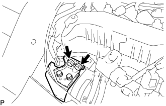
REMOVE ELECTRIC EGR CONTROL VALVE ASSEMBLY
-
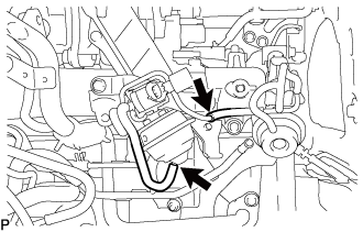
Detach the clamp and disconnect the connector from the common rail assembly.
-
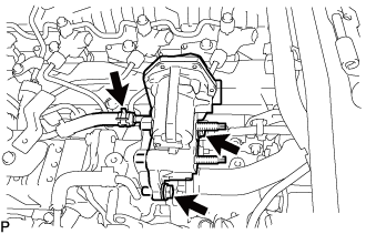
Slide the clamp and disconnect the No. 9 water by-pass hose from the electric EGR control valve assembly.
-
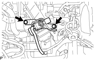
Remove the 2 bolts and electric EGR control valve assembly.
-
Remove the gasket.
-
-
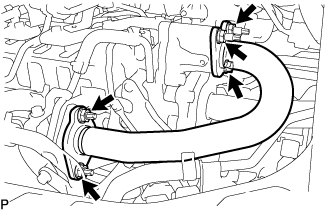
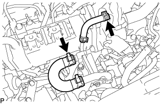
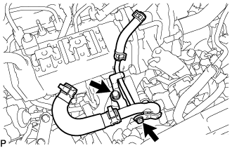
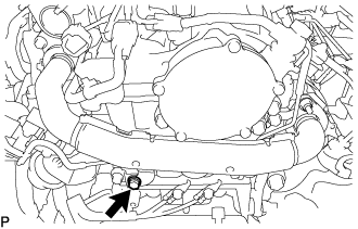
REMOVE NO. 3 WATER BY-PASS PIPE SUB-ASSEMBLY
-
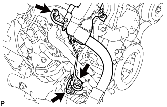
Disconnect the No. 4 fuel hose from the No. 3 water by-pass pipe sub-assembly.
-
Slide the clamp and disconnect the No. 8 water by-pass hose from the No. 3 water by-pass pipe sub-assembly.
-
Remove the 2 bolts and No. 3 water by-pass pipe sub-assembly from the No. 1 EGR cooler.
-
-
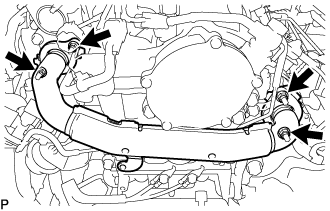
DISCONNECT NO. 4 WATER BY-PASS PIPE SUB-ASSEMBLY
-
Slide the clamp and disconnect the No. 7 water by-pass hose from the No. 1 EGR cooler.
-
Slide the clamp and disconnect the water hose from the No. 2 EGR valve assembly.
-
Remove the 2 bolts and disconnect the No. 4 water by-pass pipe sub-assembly from the intake manifold.
-
-
REMOVE EGR PIPE INSULATOR
-
Remove the 2 bolts and EGR pipe insulator from the cylinder head sub-assembly.
-
-
REMOVE NO. 1 EGR PIPE SUB-ASSEMBLY
-
Remove the bolt and disconnect the No. 1 EGR pipe sub-assembly from the vacuum transmitting pipe sub-assembly.
-
Remove the 4 nuts and the No. 1 EGR pipe sub-assembly from the exhaust manifold and EGR valve adapter.
-
Remove the 2 gaskets.
-
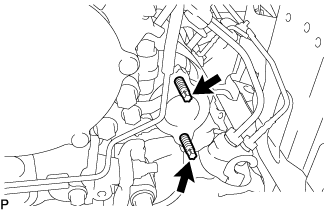
Using an E8 "TORX" socket wrench, remove the 2 stud bolts from the exhaust manifold.
-
-
REMOVE VACUUM CONTROL VALVE SET
-
Disconnect the connector from the vacuum control valve set.
-
Disconnect the 2 vacuum hoses from the vacuum control valve set and No. 2 EGR valve assembly.
-
Remove the 2 bolts and vacuum control valve set from the intake manifold.
-
-
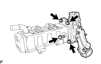
REMOVE NO. 1 EGR COOLER WITH NO. 2 EGR VALVE ASSEMBLY
-
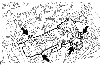
Remove the 4 bolts and No. 1 EGR cooler with No. 2 EGR valve assembly from the intake manifold.
-
-
REMOVE EGR VALVE ADAPTER
-
Remove the 2 bolts and EGR valve adapter from the No. 2 EGR valve assembly.
-
Remove the gasket.
-
-
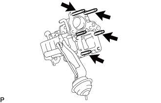
REMOVE NO. 2 EGR VALVE ASSEMBLY
-
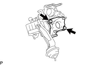
Remove the 4 bolts and No. 2 EGR valve assembly from the No. 1 EGR cooler.
-
Remove the gasket.
-
Using an E8 "TORX" socket wrench, remove the 4 stud bolts from the No. 2 EGR valve assembly.
-