КАТАЛИТИЧЕСКИЙ НЕЙТРАЛИЗАТОР В ВЫПУСКНОМ КОЛЛЕКТОРЕ УСТАНОВКА

-
INSTALL EXHAUST MANIFOLD CONVERTER SUB-ASSEMBLY
-
Set a new gasket and the exhaust manifold converter sub-assembly to the turbocharger sub-assembly.
-
Temporarily install the exhaust pipe support stay to the cylinder block sub-assembly and exhaust manifold converter sub-assembly with the 3 bolts.
-
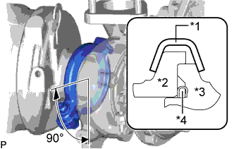
Text in Illustration *1 Exhaust Pipe Clamp *2 Exhaust Manifold Converter *3 Turbocharger Sub-assembly *4 Gasket Install a new exhaust pipe clamp to the exhaust manifold converter sub-assembly with a new nut.
- Torque:
- 18 N*m { 184 kgf*cm, 13 ft.*lbf }
-
Tighten the 3 bolts and install the exhaust pipe support stay to the cylinder block sub-assembly and exhaust manifold converter sub-assembly.
- Torque:
- 38 N*m { 387 kgf*cm, 28 ft.*lbf }
-
-
INSTALL NO. 2 EXHAUST PIPE SUPPORT STAY
-
Install the No. 2 exhaust pipe support stay to the cylinder block sub-assembly and exhaust manifold converter sub-assembly with the bolt and 2 new nuts.
- Torque:
- 38 N*m { 387 kgf*cm, 28 ft.*lbf }
-
-
INSTALL NO. 1 TURBO INSULATOR
-
Install the No. 1 turbo insulator to the exhaust manifold and turbocharger sub-assembly with the 3 bolts.
- Torque:
- 12 N*m { 122 kgf*cm, 9 ft.*lbf }
-
-
INSTALL NO. 1 EXHAUST MANIFOLD HEAT INSULATOR
-
Install the No. 1 exhaust manifold heat insulator to the exhaust manifold with the 3 bolts.
- Torque:
- 12 N*m { 122 kgf*cm, 9 ft.*lbf }
-
-
INSTALL AIR FUEL RATIO SENSOR
Tech Tips
Perform "Inspection After Repairs" after replacing the air fuel ratio sensor Click here.
-
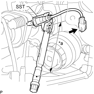
Text in Illustration *a Torque Wrench Fulcrum Length Using SST, install the air fuel ratio sensor to the front exhaust pipe.
- SST
- 09224-00012
- Torque:
- Specified tightening torque
- 44 N*m { 449 kgf*cm, 32 ft.*lbf }
Tech Tips
-
Calculate the torque wrench reading when changing the fulcrum length of the torque wrench Click here.
-
When using SST (fulcrum length of 30 mm (1.18 in.)) + torque wrench (fulcrum length of 180 mm (7.09 in.)): 38 N*m (384 kgf*cm, 28 ft.*lbf)
-
Connect the connector.
-
-
INSTALL ENGINE COVER BRACKET
-
Install the engine cover bracket to the cylinder head sub-assembly with the 2 bolts.
- Torque:
- 21 N*m { 214 kgf*cm, 15 ft.*lbf }
-
Attach the 2 clamps and connect the engine wire to the cylinder head sub-assembly.
-
-
INSTALL PIPE CLAMP
-
Install the pipe clamp to the engine cover bracket with the 3 bolts.
- Torque:
- 10 N*m { 102 kgf*cm, 7 ft.*lbf }
-
-
TEMPORARILY INSTALL NO. 2 VACUUM PIPE
-
Install a new clamp to the pipe clamp.
-
Temporarily install the No. 2 vacuum pipe to the exhaust manifold converter sub-assembly.
-
-
TEMPORARILY INSTALL NO. 1 VACUUM PIPE
-
Temporarily install the No. 1 vacuum pipe to the exhaust manifold converter sub-assembly.
-
Install a new clamp to the No. 1 vacuum pipe and No. 2 vacuum pipe with the nut.
- Torque:
- 6.0 N*m { 61 kgf*cm, 53 in.*lbf }
-
-
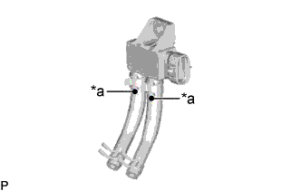
TIGHTEN NO. 2 VACUUM PIPE
-
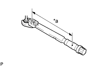
Text in Illustration *a Torque Wrench Fulcrum Length Using a 17 mm union nut wrench, tighten the No. 2 vacuum pipe.
Torque Specified tightening torque 48 N*m {489 kgf*cm, 35 ft.*lbf} Tech Tips
-
Calculate the torque wrench reading when changing the fulcrum length of the torque wrench Click here.
-
When using a union nut wrench (fulcrum length of 30 mm (1.18 in.)) + torque wrench (fulcrum length of 255 mm (10.0 in.)): 43 N*m (437 kgf*cm, 32 ft.*lbf)
-
-
-
TIGHTEN NO. 1 VACUUM PIPE
-
Text in Illustration *a Torque Wrench Fulcrum Length Using a 17 mm union nut wrench, tighten the No. 1 vacuum pipe.
Torque Specified tightening torque 48 N*m {489 kgf*cm, 35 ft.*lbf} Tech Tips
-
Calculate the torque wrench reading when changing the fulcrum length of the torque wrench Click here.
-
When using a union nut wrench (fulcrum length of 30 mm (1.18 in.)) + torque wrench (fulcrum length of 255 mm (10.0 in.)): 43 N*m (437 kgf*cm, 32 ft.*lbf)
-
-
-
INSTALL EXHAUST GAS TEMPERATURE SENSOR
-

Text in Illustration *a Torque Wrench Fulcrum Length Using a 14 mm union nut wrench, install the No. 3 exhaust gas temperature sensor to the exhaust manifold converter sub-assembly.
Torque Specified tightening torque 30 N*m {306 kgf*cm, 22 ft.*lbf} Note
-
If the No. 3 exhaust gas temperature sensor is dropped, replace it with a new.
-
When reusing the No. 3 exhaust gas temperature sensors, clean the screws and apply anti-seize compound before installing the No. 3 exhaust gas temperature sensor.
Tech Tips
-
The connector color of the No. 3 exhaust gas temperature sensor is gray.
-
Calculate the torque wrench reading when changing the fulcrum length of the torque wrench Click here.
-
When using a union nut wrench (fulcrum length of 25 mm (0.984 in.)) + torque wrench (fulcrum length of 180 mm (7.09 in.)): 26 N*m (268 kgf*cm, 19 ft.*lbf)
-
-
Text in Illustration *a Torque Wrench Fulcrum Length Using a 14 mm union nut wrench, install the No. 2 exhaust gas temperature sensor to the exhaust manifold converter sub-assembly.
Torque Specified tightening torque 30 N*m {306 kgf*cm, 22 ft.*lbf} Note
-
If the No. 2 exhaust gas temperature sensor is dropped, replace it with a new.
-
When reusing the No. 2 exhaust gas temperature sensors, clean the screws and apply anti-seize compound before installing the No. 2 exhaust gas temperature sensor.
Tech Tips
-
The connector color of the No. 2 exhaust gas temperature sensor is black.
-
Calculate the torque wrench reading when changing the fulcrum length of the torque wrench Click here.
-
When using a union nut wrench (fulcrum length of 25 mm (0.984 in.)) + torque wrench (fulcrum length of 180 mm (7.09 in.)): 26 N*m (268 kgf*cm, 19 ft.*lbf)
-
-
Text in Illustration *a Torque Wrench Fulcrum Length Using a 14 mm union nut wrench, install the exhaust gas temperature sensor to the exhaust manifold converter sub-assembly.
Torque Specified tightening torque 30 N*m {306 kgf*cm, 22 ft.*lbf} Note
-
If the exhaust gas temperature sensor is dropped, replace it with a new.
-
When reusing the exhaust gas temperature sensors, clean the screws and apply anti-seize compound before installing the exhaust gas temperature sensor.
Tech Tips
-
The connector color of the exhaust gas temperature sensor is white.
-
Calculate the torque wrench reading when changing the fulcrum length of the torque wrench Click here.
-
When using a union nut wrench (fulcrum length of 25 mm (0.984 in.)) + torque wrench (fulcrum length of 180 mm (7.09 in.)): 26 N*m (268 kgf*cm, 19 ft.*lbf)
-
-
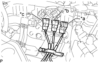
Text in Illustration *a White *b Black *c Gray Attach the 3 colored connectors to the pipe clamp in the positions shown in the illustration.
-
Close the clamp of the pipe clamp, and install the bolt.
- Torque:
- 10 N*m { 102 kgf*cm, 7 ft.*lbf }
Note
Arrange the exhaust gas temperature sensor wires so that they do not contact each other.
-
Connect the No. 3 exhaust gas temperature sensor to the No. 1 vacuum pipe.
- Torque:
- 10 N*m { 102 kgf*cm, 7 ft.*lbf }
-
Connect the 3 connectors to the 3 exhaust gas temperature sensors.
-
-
INSTALL DIFFERENTIAL PRESSURE SENSOR
-
Text in Illustration *a Paint Mark Install the 2 air hoses to the differential pressure sensor, and slide the 2 clamps to secure the 2 hoses.
Tech Tips
Make sure the paint mark of the air hose side the differential pressure sensor.
-
Connect the 2 air hoses to the No. 1 vacuum pipe and No. 2 vacuum pipe, and slide the 2 clamps to secure the 2 hoses.
-
Install the differential pressure sensor to the pipe clamp with the bolt.
- Torque:
- 10 N*m { 102 kgf*cm, 7 ft.*lbf }
-
Connect the connector to the differential pressure sensor.
-
-
INSTALL ENGINE ASSEMBLY