ТОПЛИВНЫЙ НАСОС УСТАНОВКА
-
INSTALL FUEL SUCTION WITH PUMP AND GAUGE TUBE ASSEMBLY
-
Apply a light coat of gasoline or grease to a new fuel suction tube set gasket and install the fuel suction tube set gasket to the fuel tank assembly.
-
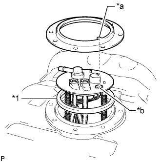
Text in Illustration *1 Fuel Suction Tube Set Gasket *a Protrusion *b Groove Align the protrusion of the fuel tank vent tube set plate with the groove of the fuel suction with pump and gauge tube assembly.
Note
Be careful not to bend the arm of the fuel sender gauge assembly.
-
Install the fuel tank vent tube set plate with the 8 bolts.
- Torque:
- 6.0 N*m { 61 kgf*cm, 53 in.*lbf }
-
Connect the fuel tank wire connector.
-
-
CONNECT FUEL TANK MAIN TUBE SUB-ASSEMBLY
-
Push the fuel tank main tube sub-assembly into the plug of the fuel suction with pump and gauge tube assembly, and then install the tube joint clip.
Note

-
Check that there are no scratches or foreign matter on the connecting parts.
-
Check that the fuel tube joints are inserted securely.
-
Check that the tube joint clips are on the collars of the fuel tube joints.
-
After installing the tube joint clips, check that the fuel tube joints cannot be pulled off.
Text in Illustration *1 Fuel Tube Joint *2 Fuel Tube *3 O-Ring *4 Tube Joint Clip *a CORRECT *b INCORRECT -
-
-
CONNECT FUEL TANK RETURN TUBE
-
Push the fuel tank return tube into the plug of the fuel suction with pump and gauge tube assembly, and then install the tube joint clip.
Note
-
Check that there are no scratches or foreign matter on the connecting parts.
-
Check that the fuel tube joints are inserted securely.
-
Check that the tube joint clips are on the collars of the fuel tube joints.
-
After installing the tube joint clips, check that the fuel tube joints cannot be pulled off.
Text in Illustration *1 Fuel Tube Joint *2 Fuel Tube *3 O-Ring *4 Tube Joint Clip *a CORRECT *b INCORRECT -
-
-
CONNECT NO. 1 FUEL EVAPORATION TUBE SUB-ASSEMBLY
-
Connect the No. 1 fuel evaporation tube sub-assembly to the fuel suction with pump and gauge tube sub-assembly Click here.
-
-
INSTALL FUEL TANK INSPECTION HOLE COVER
-
Install the fuel tank inspection hole cover with the 4 screws.
-
-
CONNECT CABLE TO NEGATIVE BATTERY TERMINAL
Note
When disconnecting the cable, some systems need to be initialized after the cable is reconnected Click here.
-
INSPECT FOR FUEL LEAK
-
Make sure that there are no fuel leaks after performing maintenance on the fuel system.
-
Connect the GTS to the DLC3.
-
Turn the ignition switch to ON and turn the GTS on.
Note
Do not start the engine.
-
Enter the following menus: Powertrain / Engine and ECT / Active Test / Control the Fuel Pump / Speed.
-
Check that there are no fuel leaks from the fuel system.
If there are fuel leaks, repair or replace parts as necessary.
-
Turn the ignition switch off.
-
Disconnect the GTS from the DLC3.
-
-