ТОПЛИВНАЯ ФОРСУНКА УСТАНОВКА

-
INSTALL NOZZLE HOLDER AND NOZZLE SET
-
Place 4 new injection nozzle seat gaskets and 4 injection nozzle seats into the injection nozzle holes of the cylinder head.
-
Using SST, install the 4 nozzle holder and nozzle sets.
- SST
- 09268-64010 ( 09268-64020 )
- Torque:
- 64 N*m { 650 kgf*cm, 47 ft.*lbf }
-
-
INSTALL NOZZLE LEAKAGE PIPE ASSEMBLY
-
Install 4 new ring packing washers and the leakage pipe assembly with the 4 nuts.
- Torque:
- 30 N*m { 300 kgf*cm, 22 ft.*lbf }
-
Connect the fuel hose to the leakage pipe.
-
-
INSTALL GLOW PLUG NO.1 CONNECTOR
- Torque:
- 1.0 N*m { 10 kgf*cm, 9 in.*lbf }
-
INSTALL INJECTION PIPE SET
-
Connect the 2 lower clamps on the intake manifold.
-
Install the 4 injection pipes.
- Torque:
- 25 N*m { 250 kgf*cm, 18 ft.*lbf }
-
Secure the injection pipes with the 2 upper pipe clamps and 2 nuts.
- Torque:
- 5.0 N*m { 50 kgf*cm, 44 in.*lbf }
-
-
BLEED INJECTION PIPE
-
Move the priming pump in the upper part of the fuel filter assembly up and down, and fill the injection pump assembly and fuel system with fuel.
-
Loosen one of the union nuts (in the nozzle side).
-
Crank the engine until fuel comes out from the union nut (in the nozzle side).
-
Tighten the union nut.
- Torque:
- 25 N*m { 250 kgf*cm, 18 ft.*lbf }
-
The above operation should be carried out each injection pipe.
-
-
INSTALL VENTURI ASSEMBLY
-
Install a new gasket and venturi.
-
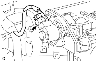
Connect the throttle control motor connector.
-
Connect the throttle open switch connector.
-
-
INSTALL INTAKE AIR CONNECTOR BRACKET
-
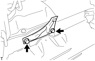
Установите кронштейн соединителя впуска воздуха и закрепите его 2 болтами.
- Torque:
- 18 Н*м { 184 кгс*см, 13 фунт-сила-футов }
-
-
INSTALL INTAKE AIR CONNECTOR SUB-ASSEMBLY
-
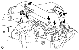
Install a new gasket and intake air connector with the bolt and 3 nuts.
- Torque:
- bolt
- 18 N*m { 184 kgf*cm, 13 ft.*lbf }
- Nut
- 12 N*m { 122 kgf*cm, 9 ft.*lbf }
-
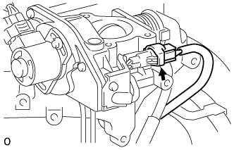
Connect the turbo pressure sensor connector.
-
Connect the ventilation hose.
-
-
CONNECT AIR CLEANER HOSE NO.2
-
Install the air cleaner hose No.2 with the clamp.
-
-
INSTALL ENGINE SERVICE HOLE SUB COVER SUB-ASSEMBLY
-
Установите крышку технологического отверстия двигателя и закрепите ее 5 болтами.
- Torque:
- 13 Н*м { 133 кгс*см, 10 фунт-сила-футов }
-
-
INSTALL FRONT DOOR SCUFF PLATE RH
-
INSTALL FRONT SEAT ASSEMBLY RH (for Hi-back Seat Type)
Порядок выполнения работ такой же, как для левой стороны. (см. стр. Click here)
-
INSTALL FRONT SEAT ASSEMBLY RH (for Low-back Seat Type)
Порядок выполнения работ такой же, как для левой стороны. (см. стр. Click here)
-
CHECK FOR FUEL LEAKS
-
Check that there are no fuel leaks anywhere on the fuel system after doing maintenance.
Tech Tips
When checking for fuel leaks, make sure that there is pressure in the fuel line.
-