ТОПЛИВНАЯ ФОРСУНКА УСТАНОВКА

-
INSTALL INJECTOR ASSEMBLY
Note
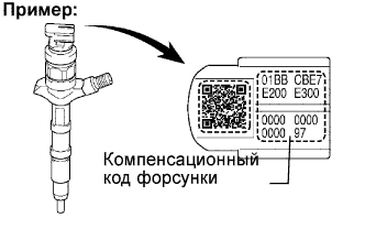
It is necessary to register the injector compensation code manually in the ECM using the intelligent tester, as each injector assembly has a different injection characteristic.
-
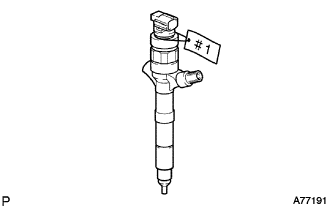
Put tags with cylinder numbers (#1 to #4) onto the new injector assembly in order to make sure of the right combinations with the right cylinders.
Standard Resistance 0.85 to 1.05 Ω at 20°C (69°F) -
Register the injector compensation code manually Click here.
-
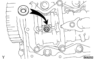
Install a new injection nozzle sheet to the cylinder head.
-
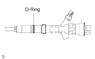
Install a new O-ring.
Tech Tips
Apply a light coat of engine oil to the O-ring.
-
Install the injector assembly to each cylinder referring to the tags with cylinder numbers (#1 to #4).
Note
If the wrong injector assembly is installed on the cylinder, rough idling or noise may occur.
-
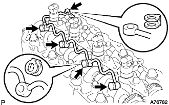
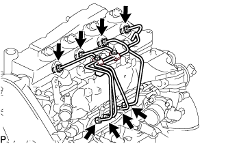
Temporarily install the 4 injection pipes.
Note
In case of having replaced the injector, replace the injection pipe, too.
Tech Tips
Tighten the union nuts of the injection pipes by hand until them cannot turn.
-
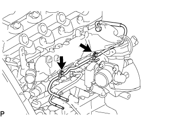
Apply a light coat of engine oil to the 4 hollow screws and union bolt.
-
Temporarily install the nozzle leakage pipe assembly and 5 new nozzle leakage pipe gaskets and tighten the 4 hollow screws, union bolt by hand until them cannot turn.
Note
Confirm the deformation and damage the injector hollow screws, and union bolt.
-
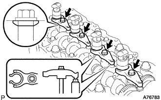
Install the 4 nozzle holder clamps and 4 new washers with the 4 bolts as show in the illustration.
-
Tighten the new washers and 4 bolts.
- Torque:
- 22 N*m { 220 kgf*cm, 16 ft.*lbf }
Note
-
Pay attention the direction of washers.
-
Clip the injector at the fork portion with a clamp which is set on the head of the cam cap bolt. At this time, check that the clamp does not hold the injector at the part where the spring is attached.
-
Temporarily torque the clamp bolts by hand until the bearing surface of the bolt touches the washer, then tighten them by the specified torque.
-
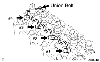
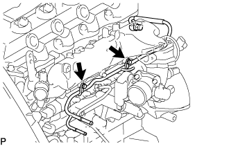
Tighten the 4 hollow screws from #1 to #4 in order.
- Torque:
- 16 N*m { 163 kgf*cm, 12 ft.*lbf }
-
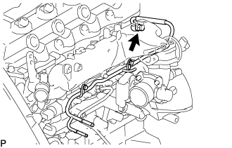
Tighten the union bolt.
- Torque:
- 13 N*m { 130 kgf*cm, 9 ft.*lbf }
Note
In case of overtightening the nozzle leakage, replace it with a new one.
-
Remove the injection pipe No.1, No.2, No.3 and No.4.
-
-
CHECK NOZZLE LEAKAGE PIPE LEAK
-
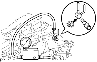
Using SST, install the nozzle leakage pipe No.2 and a new gasket.
- SST
- 09280-00010
- Torque:
- 21 N*m { 215 kgf*cm, 15 ft.*lbf }
Nozzle leakage pipe No.2 23762 - 27010 Gasket 90904 - 30012 -
Using SST (turbo charge pressure gauge), set the SST to the leakage pipe No.2 and maintain 250 kPa (2.5 kgf/cm2, 37 psi) of pressure for 60 seconds to check that there are no leaks from the nozzle leakage pipe assembly.
Note
Be sure to keep specified pressure, preventing form leakage.
Tech Tips
-
Apply a coat of engine oil to the nozzle leakage pipe assembly connection, and check that no bubbles come from the nozzle leakage pipe assembly.
-
Check that indication on the SST (turbo charger pressure gauge) does not go down while pressure is applied.
-
-
Remove the SST, nozzle leakage pipe assembly No.2.
-
-
INSTALL NOZZLE LEAKAGE PIPE ASSEMBLY NO.2
-
Temporarily install the nozzle leakage pipe assembly No.2 with the 2 bolts.
-
Install the check valve nozzle leakage pipe assembly No.2 and a new gasket.
- Torque:
- 21 N*m { 214 kgf*cm, 15 ft.*lbf }
-
Tighten the 2 bolts.
- Torque:
- 13 N*m { 133 kgf*cm, 10 ft.*lbf }
-
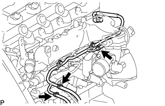
Install the 3 fuel hoses on the nozzle leakage pipe assembly No.2.
-
-
INSTALL CYLINDER HEAD COVER SUB-ASSEMBLY
-

Install 4 new No. 3 cylinder head cover gaskets to the cylinder head cover as shown in the illustration.
Note
-
Do not install the gaskets at an angle.
-
Keep the lip of the gasket free from foreign materials.
-
-
Install a new cylinder head cover gasket to the cylinder head cover.
-
Remove old seal packing (FIPG) from the cylinder head.
-
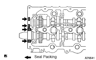
Apply a seal packing to the specific places described in the illustration.
Seal packing Toyota Genuine Seal Packing Black, Three Bond 1207B or equivalent Note
-
After applying the seal packing, parts must be assembled within 3 minutes, and then tighten within 15 minutes.
-
Otherwise the material must be removed and reapplied.
-
Do not start the engine 2 hour after the installation.
-
-
Install the cylinder head cover with 10 bolts and 2 nuts.
- Torque:
- 9.0 N*m { 92 kgf*cm, 80 in.*lbf }
-
Connect the ventilation hose.
-
Install a new nozzle holder seal.
-
-
INSTALL INJECTION PIPE
- SST
- 09023-12701
Note
-
When replacing the fuel injector, common rail, or cylinder head with a new one, replace injection pipes No. 1, No. 2, No. 3, and No. 4.
-
Keep clean the joint of the injection pipe.
-
Install the injection pipes.
-
Temporarily install the 4 injection pipes.
-
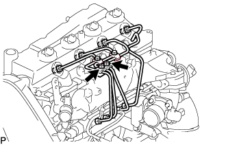
Install the injection pipe clamp No.3 in 2 nuts.
- Torque:
- 5.0 N*m { 51 kgf*cm, 44 in.*lbf }
-
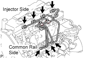
Fasten the union sequentially, from the injection pipe common rail to the injector, using SST.
- SST
- 09023-12701
- Torque:
- Use union nut wrench and torque wrench
- 32 N*m { 326 kgf*cm, 24 ft.*lbf }
-
-
INSTALL OIL LEVEL GAGE GUIDE
-
Установите на трубку щупа проверки уровня масла новое уплотнительное кольцо.
-
Нанесите на уплотнительное кольцо тонкий слой моторного масла.
-
Установите трубку щупа проверки уровня масла и закрепите ее болтом.
- Torque:
- 8,0 Н*м { 82 кгс*см, 71 фунт-сила-дюйм }
-
Установите щуп проверки уровня масла.
-
-
INSTALL INTAKE AIR CONNECTOR (w/o EGR Valve)
-
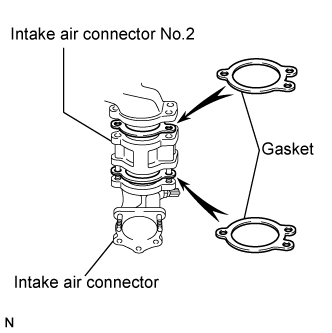
Temporarily install 2 new gaskets and intake air connector No.2 to the intake air connector.
-
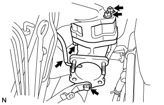
Temporarily tighten the intake air connector assembly with the bolt and 2 nuts.
-
Tighten the manifold stay with the bolt.
-
Tighten the intake air connector with the bolt and 2 nuts.
-
Install the vacuum hose to the intake air connector.
-
-
TEMPORARILY TIGHTEN ELECTRIC EGR CONTROL VALVE ASSEMBLY (w/ EGR Valve)
-
Temporarily tighten the EGR valve assembly with the sensor.
-
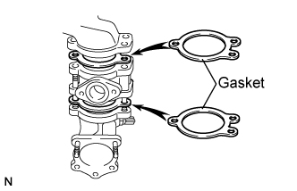
Install 2 new gaskets and the EGR valve to the intake air connector as shown in the illustration.
-
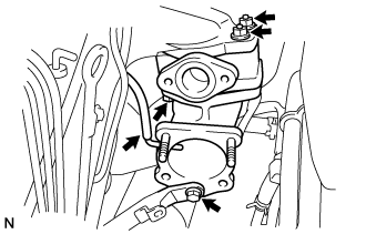
Temporarily tighten the intake air connector with EGR valve assembly to the intake manifold with the bolt and the 2 nuts.
-
Install the vacuum hose to the intake air connector.
-
Temporarily tighten the manifold stay with the bolt.
-
Connect the EGR valve position sensor connector.
-
Connect the intake air temperature sensor connector.
-
-
Install the vacuum regulating valve.
-
Install the vacuum regulating valve with the 2 bolts.
- Torque:
- 20 N*m { 204 kgf*cm, 15 ft.*lbf }
-
Connect the 2 vacuum hoses and the regulating valve connector.
-
-
-
INSTALL EGR PIPE SUB-ASSEMBLY NO.1 (w/ EGR Valve)
-
Install the 2 gaskets to the cylinder head and EGR pipe sub-assembly as shown in the illustration.
-
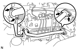
Install the EGR pipe sub-assembly with the 2 bolts and 2 nuts.
- Torque:
- 13 N*m { 133 kgf*cm, 10 ft.*lbf }
-
Tighten the intake air connector with the bolt and the 2 nuts.
- Torque:
- 20 N*m { 204 kgf*cm, 15 ft.*lbf }
-
Tighten the manifold stay.
- Torque:
- 19 N*m { 194 kgf*cm, 14 ft.*lbf }
-
-
REMOVE EGR PIPE SUB-ASSEMBLY NO.1 (w/ EGR Valve)
-
Remove the 3 bolts, the 2 nuts, and the EGR pipe sub-assembly.
-
Remove the 2 gaskets.
-
-
INSTALL DIESEL THROTTLE BODY ASSEMBLY
Note
After removing and installing, or replacing the throttle body, be sure to perform the operation check.
-
Install a new gasket to intake air connector.
-
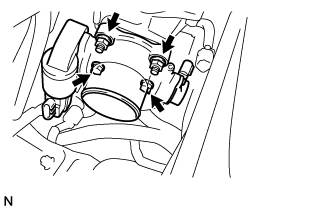
Install the throttle body with the 2 bolts and the 2 nuts.
- Torque:
- 20 N*m { 204 kgf*cm, 15 ft.*lbf }
-
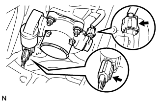
Connect the 2 throttle body connectors.
-
-
INSTALL AIR HOSE NO.4
-
Install the air hose No.4 with the 2 clamps.
- Torque:
- 6.0 N*m { 61 kgf*cm, 53 in.*lbf }
-
-
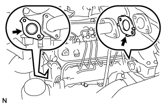
INSTALL EGR PIPE SUB-ASSEMBLY NO.1 (w/ EGR Valve)
-
Install 2 new gaskets to the cylinder head and the EGR pipe sub-assembly No.1 as shown in the illustration.
-
Install the EGR pipe with the 2 bolts and the 2 nuts.
- Torque:
- 13 N*m { 133 kgf*cm, 10 ft.*lbf }
-
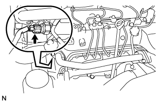
Connect the fuel pressure sensor connector.
-
-
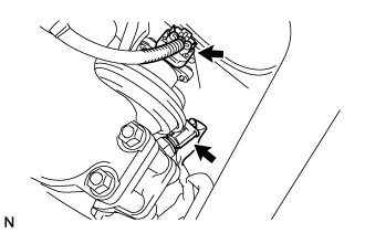
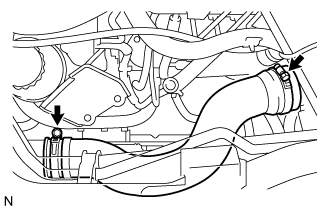
CONNECT OIL RETURN HOSE
-
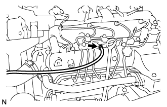
Connect the oil return hose with the clip.
-
-
INSTALL VANE PUMP OIL RESERVOIR ASSEMBLY
-
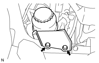
Install the vane pump oil reservoir assembly with the 2 bolts.
- Torque:
- 8.0 N*m { 82 kgf*cm, 71 in.*lbf }
-
-
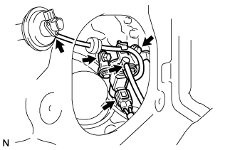
INSTALL ENGINE SERVICE HOLE SUB COVER SUB-ASSEMBLY
-
Установите вспомогательную крышку технологического отверстия двигателя и закрепите ее 5 болтами.
- Torque:
- 13 Н*м { 133 кгс*см, 10 фунт-сила-футов }
-
-
INSTALL FRONT DOOR SCUFF PLATE RH
-
INSTALL FRONT SEAT ASSEMBLY RH (for Hi-back Seat Type)
-
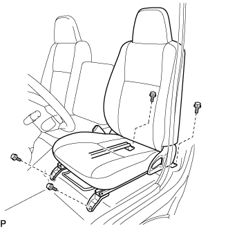
Подсоедините разъем замка ремня безопасности переднего сиденья в сборе и установите переднее сиденье в сборе.
-
Совместите штырь регулятора переднего сиденья в сборе с отверстиями в кузове.
-
Сдвиньте переднее сиденье в сборе в крайнее заднее положение.
Note
Убедитесь, что переднее сиденье в сборе надежно зафиксировано.
-
Предварительно затяните 2 болта на передней стороне переднего сиденья в сборе.
-
Выдвиньте переднее сиденье в сборе до упора вперед.
Note
Убедитесь, что переднее сиденье в сборе надежно зафиксировано.
-
Предварительно затяните 2 болта на задней стороне переднего сиденья в сборе.
-
Сдвиньте переднее сиденье в сборе в крайнее заднее положение.
Note
Убедитесь, что переднее сиденье в сборе надежно зафиксировано.
-
Полностью затяните 2 болта на передней стороне переднего сиденья в сборе, сначала наружный, а затем внутренний.
- Torque:
- 39 Н*м { 398 кгс*см, 29 фунт-сила-футов }
-
Выдвиньте переднее сиденье в сборе до упора вперед.
Note
Убедитесь, что переднее сиденье в сборе надежно зафиксировано.
-
Полностью затяните 2 болта на задней стороне переднего сиденья в сборе, сначала наружный, а затем внутренний.
- Torque:
- 39 Н*м { 398 кгс*см, 29 фунт-сила-футов }
-
-
INSTALL FRONT SEAT ASSEMBLY RH (for Low-back Seat Type)
-
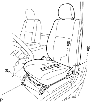
Подсоедините разъем замка ремня безопасности переднего сиденья в сборе и установите переднее сиденье в сборе.
-
Совместите штырь регулятора переднего сиденья в сборе с отверстиями в кузове.
-
Сдвиньте переднее сиденье в сборе в крайнее заднее положение.
Note
Убедитесь, что переднее сиденье в сборе надежно зафиксировано.
-
Предварительно затяните 2 болта на передней стороне переднего сиденья в сборе.
-
Выдвиньте переднее сиденье в сборе до упора вперед.
Note
Убедитесь, что переднее сиденье в сборе надежно зафиксировано.
-
Предварительно затяните 2 болта на задней стороне переднего сиденья в сборе.
-
Сдвиньте переднее сиденье в сборе в крайнее заднее положение.
Note
Убедитесь, что переднее сиденье в сборе надежно зафиксировано.
-
Полностью затяните 2 болта на передней стороне переднего сиденья в сборе, сначала наружный, а затем внутренний.
- Torque:
- 39 Н*м { 398 кгс*см, 29 фунт-сила-футов }
-
Выдвиньте переднее сиденье в сборе до упора вперед.
Note
Убедитесь, что переднее сиденье в сборе надежно зафиксировано.
-
Полностью затяните 2 болта на задней стороне переднего сиденья в сборе, сначала наружный, а затем внутренний.
- Torque:
- 39 Н*м { 398 кгс*см, 29 фунт-сила-футов }
-
-
CHECK INJECTOR COMPENSATION CODE
-
Check that the injector compensation code registered in the injector assembly installed on each cylinder match the ones registered in the ECM Click here.
-
-
ADD ENGINE COOLANT
-
Надежно затяните сливные пробки.
-
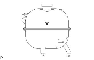
Залейте охлаждающую жидкость в расширительный бачок радиатора до верха горловины.
Номинальный объем Параметр / Устройство Заданные условия Для моделей без подогревателя 13,2 литра (13,9 кварты США, 11,6 английской кварты) Для моделей с передним подогревателем 14,2 литра (15,0 кварты США, 12,5 английской кварты) Для моделей с передним и задним подогревателями 16,2 л (17,1 кварты США, 14,3 английской кварты) Note
Не доливайте простую воду вместо охлаждающей жидкости двигателя.
Tech Tips
-
Использование неподходящей охлаждающей жидкости может привести к повреждению системы охлаждения двигателя.
-
Разрешается использовать только охлаждающую жидкость "TOYOTA Super Long Life Coolant" или аналогичную высококачественную охлаждающую жидкость на основе этиленгликоля (а не на силикатной, аминовой, нитритной или борнокислой основе), изготовленную по гибридной технологии органических кислот с длительным сроком годности (охлаждающая жидкость, изготовленная по гибридной технологии органических кислот, состоит из низкофосфатных соединений и органических кислот).
-
-
Ослабьте прокачной штуцер корпуса отводящего патрубка.
-
После удаления воздуха и слива охлаждающей жидкости двигателя надежно затяните прокачной штуцер.
- Torque:
- 8,0 Н*м { 82 кгс*см, 71 фунт-сила-дюйм }
-
Долейте охлаждающую жидкость в расширительный бачок радиатора до отметки B и установите пробку расширительного бачка радиатора.
-
Прогревайте двигатель, пока не откроется термостат.
-
Когда термостат откроется, несколько минут прокачивайте охлаждающую жидкость двигателя.
Tech Tips
Время открывания термостата можно проверить, сжав шланг радиатора № 3 рукой и определив, когда охлаждающая жидкость начинает поступать в шланг.
-
-
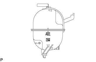
После охлаждения двигателя убедитесь, что уровень охлаждающей жидкости двигателя находится между отметками "LOW" и "FULL".
-
-
CHECK FOR ENGINE COOLANT LEAKAGE
-
Снимите пробку радиатора.
CAUTION:
Не снимайте пробку радиатора, пока двигатель и радиатор не остынут. Выброс горячей охлаждающей жидкости и пара под давлением может стать причиной серьезных ожогов.
-
Убедитесь, что вокруг пробки и наливной горловины радиатора нет чрезмерных отложений ржавчины и окалины. Охлаждающая жидкость не должна содержать масло.
Tech Tips
При наличии избыточных загрязнений очистите каналы для охлаждающей жидкости и замените охлаждающую жидкость.
-
Установите на место пробку радиатора.
-
-
BLEED FUEL LINE
-
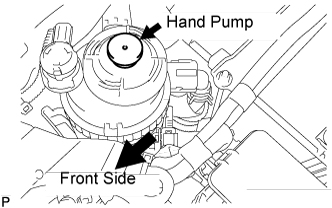
Using the hand pump, bleed air from the fuel system until pumping becomes difficult.
-
-
INSTALL ENGINE UNDER COVER NO.1 (w/ Engine Under Cover)
-
CONNECT BATTERY NEGATIVE CABLE
-
INSTALL BATTERY SERVICE HOLE COVER
-
CHECK FOR FUEL LEAKS
-
PERFORM ACTIVE TEST
-
Connect the GTS to the DLC3.
-
Turn the ignition switch on.
-
Turn the GTS on.
-
Enter the following menus: Powertrain / Engine and ECT / Active Test.
-
Perform the Active Test.
Tester Display Test Details Control Range Diagnostic Notes Test the Fuel Leak Pressurizes common rail internal fuel pressure, and checks for fuel leaks Stop/Start
-
Fuel pressure inside common rail pressurized to specified value and engine speed increased to 2,000 rpm when ON is selected
-
Above conditions preserved while test is ON
-
-
-