ТОПЛИВНЫЙ БАК УСТАНОВКА
-
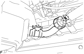
INSTALL FUEL SENDER GAUGE ASSEMBLY
-
Install the fuel hose grommet onto the fuel tank assembly.
-
Install a new fuel suction tube set gasket, the fuel pump gauge retainer and the fuel sender gauge assembly with the 8 bolts.
- Torque:
- 6.0 N*m { 61 kgf*cm, 53 in.*lbf }
-
Install the fuel tank wire, No. 1 fuel evaporation tube sub-assembly, fuel tank main tube sub-assembly and fuel tank return tube sub-assembly onto the fuel sender gauge assembly.
-
-
INSTALL FUEL TANK ASSEMBLY
-
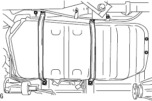
Using the transmission jack, install the 2 fuel tank band sub-assemblies and fuel tank assembly with the 6 bolts.
- Torque:
- 45 N*m { 459 kgf*cm, 32 ft.*lbf }
-
Connect the No. 3 parking brake cable with the bolt.
- Torque:
- 15 N*m { 153 kgf*cm, 11 ft.*lbf }
-
-
CONNECT NO. 3 FUEL HOSE
-
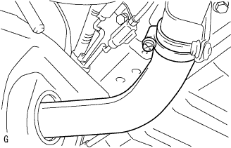
Connect the No. 3 fuel hose, and tighten the clamp bolt.
-
-
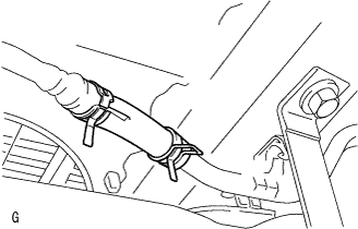
INSTALL FUEL HOSE PROTECTOR
-
Install the fuel hose protector to the fuel tank to filler pipe hose and attach the 2 claws.
-
-
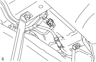
CONNECT FUEL TANK BREATHER TUBE
-
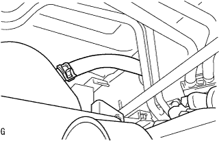
Secure the fuel tank breather tube to the fuel tank assembly with the clip.
-
-
CONNECT FUEL TANK MAIN TUBE SUB-ASSEMBLY
-
Connect the fuel tank main tube sub-assembly with the clip.
-
-
CONNECT FUEL TANK RETURN TUBE
-
Connect the fuel return tube Click here.
-
-
CONNECT FUEL TANK WIRE
-
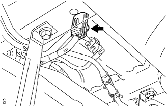
Connect the fuel tank wire.
-
-
INSTALL PROPELLER SHAFT ASSEMBLY
-
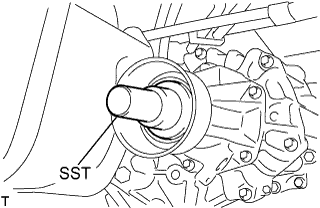
Снимите SST с удлинителя картера трансмиссии.
-
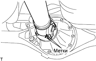
Установите карданный вал в сборе в удлинитель картера трансмиссии.
-
Совместите метки на фланце карданного вала и фланце дифференциала.
-
Закрепите карданный вал в сборе с помощью 4 гаек, 4 болтов и 4 шайб.
- Torque:
- 74 Н*м { 755 кгс*см, 54 фунт-сила-фута }
-
-
INSPECT FOR FUEL LEAK
Note
-
During Active Test mode, the engine speed becomes high and the combustion noise becomes loud, so pay attention.
-
During Active Test mode, the fuel pressure becomes high. Be extremely careful not to expose your eyes, hands, or body to escaping fuel.
Tech Tips
Using the GTS to perform Active Tests allow relays, VSVs, actuators and other items to be operated without removing any parts. This non-intrusive functional inspection can be very useful because intermittent operation may be discovered before parts or wiring is disturbed. Performing Active Tests early in troubleshooting is one way to save diagnostic time. Data List information can be displayed while performing Active Tests.
-
Check that there are no leaks from any part of the fuel system when the engine is stopped. If there is fuel leakage, repair or replace parts as necessary.
-
Start the engine and check that there are no leaks from any part of the fuel system. If there is fuel leakage, repair or replace parts as necessary.
-
Disconnect the return hose from the common rail assembly.
-
Start the engine and check for fuel leaks from the return pipe. If there is fuel leakage, replace the common rail assembly.
-
Perform the Active Test.
-
Connect the GTS to the DLC3.
-
Turn the ignition switch to ON.
-
Turn the GTS on.
-
Enter the following menus: Powertrain / Engine / Active Test / Test the Fuel Leak.
-
If the GTS is not available, fully depress the accelerator pedal quickly. Increase the engine speed to the maximum and maintain that speed for 2 seconds. Repeat this operation several times.
-
Check that there are no leaks from any part of the fuel system.
Tech Tips
A return pipe leakage of less than 10 cc (0.6 cu in.) per minute is acceptable.
If there is fuel leakage, repair or replace parts as necessary.
-
-
Reconnect the return hose to the common rail assembly.
-