ТОПЛИВНАЯ СИСТЕМА ДВИГАТЕЛЯ COMMON RAIL УСТАНОВКА

Note
-
When replacing the parts in the following chart (A), replace the No. 1 injection pipe sub-assembly, No. 2 injection pipe sub-assembly and/or fuel inlet pipe sub-assembly with new ones.
Replaced Parts (A) Pipes Requiring New Replacement
-
Injector assembly (including shuffling the injector assemblies between the cylinders)
-
Common rail assembly
-
Cylinder head sub-assembly
-
No. 1 injection pipe sub-assembly
-
No. 2 injection pipe sub-assembly
Supply pump assembly Fuel inlet pipe sub-assembly
-
Common rail assembly
-
Cylinder block sub-assembly
-
Cylinder head sub-assembly
-
Cylinder head gasket
-
Timing chain case assembly
-
No. 1 injection pipe sub-assembly
-
No. 2 injection pipe sub-assembly
-
Fuel inlet pipe sub-assembly
-
-
After removing the No. 1 injection pipe sub-assembly, No. 2 injection pipe sub-assembly and/or fuel inlet pipe sub-assembly, clean them with a brush and compressed air.
-
The injector assembly is a precision instrument. Do not use the injector assembly if it is struck or dropped.
-
Make sure foreign matter does not enter the fuel path.
-
INSTALL COMMON RAIL ASSEMBLY
-
Install the common rail assembly with the 2 nuts.
- Torque:
- 21 N*m { 214 kgf*cm, 15 ft.*lbf }
-
Connect the fuel pressure sensor connector to the common rail assembly.
-
Attach the wire harness clamp.
-
-
INSTALL NO. 4 FUEL HOSE
-
Connect the No. 4 fuel hose to the common rail assembly, and slide the clamp to secure it.
-
-
TEMPORARILY INSTALL NO. 1 AND NO. 2 INJECTION PIPE SUB-ASSEMBLY
-
Temporarily install the 2 No. 2 injection pipe sub-assemblies with the 4 union nuts.
-
Temporarily install the 2 No. 1 injection pipe sub-assemblies with the 4 union nuts.
-
-
TIGHTEN NO. 1 AND NO. 2 INJECTION PIPE SUB-ASSEMBLY
-
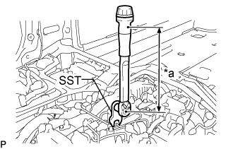
Text in Illustration *a Torque Wrench Fulcrum Length Using SST, tighten the 8 union nuts of the No. 1 and No. 2 injection pipe sub-assemblies.
- Torque:
- Specified tightening torque
- 40 N*m { 408 kgf*cm, 30 ft.*lbf }
Tech Tips
-
Calculate the torque wrench reading when changing the fulcrum length of the torque wrench.
-
When using SST (fulcrum length of 50 mm (1.97 in.)) + torque wrench (fulcrum length of 180 mm (7.09 in.)): 31 N*m (316 kgf*cm, 23 ft.*lbf)
-
-
INSTALL FUEL INLET PIPE SUB-ASSEMBLY
Note
When replacing the fuel supply pump assembly, it is necessary to replace the fuel inlet pipe sub-assembly, No. 1 injection pipe clamp and No. 2 injection pipe clamp with a new one. Keep the fuel inlet pipe sub-assembly free of foreign matter.
-
Temporarily install the fuel inlet pipe sub-assembly.
-
Install a new No. 1 injection pipe clamp and No. 2 injection pipe clamp with the 2 bolts.
- Torque:
- 10 N*m { 102 kgf*cm, 7 ft.*lbf }
-
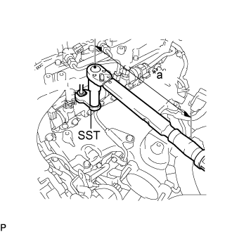
Text in Illustration *a Torque Wrench Fulcrum Length Using SST, tighten the fuel inlet pipe sub-assembly union nut on the common rail side sub-assembly.
- SST
- 09245-11010
- Torque:
- Specified tightening torque
- 40 N*m { 408 kgf*cm, 30 ft.*lbf }
Tech Tips
-
Calculate the torque wrench reading when changing the fulcrum length of the torque wrench.
-
When using a union nut wrench (fulcrum length of 50 mm (1.97 in.)) + torque wrench (fulcrum length of 180 mm (7.09 in.)): 31 N*m (316 kgf*cm, 23 ft.*lbf)
-
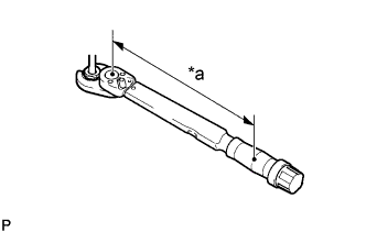
Text in Illustration *a Torque Wrench Fulcrum Length Using a 19 mm union nut wrench, tighten the fuel inlet pipe sub-assembly union nut on the fuel supply pump assembly side.
- Torque:
- Specified tightening torque
- 48 N*m { 489 kgf*cm, 35 ft.*lbf }
Tech Tips
-
Calculate the torque wrench reading when changing the fulcrum length of the torque wrench.
-
When using a union nut wrench (fulcrum length of 30 mm (1.18 in.)) + torque wrench (fulcrum length of 180 mm (7.09 in.)): 41 N*m (418 kgf*cm, 30 ft.*lbf)
-
-
INSTALL NO. 4 FUEL PIPE SUB-ASSEMBLY
-
Temporarily install the No. 4 fuel pipe sub-assembly and 2 new gaskets with the 2 union bolts and bolt.
-
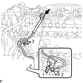
Text in Illustration 
Union Bolt 
Bolt 
Supply Pump Hollow Screw Tighten the union bolt and bolt in the order shown in the illustration.
- Torque:
- union bolt
- 42 N*m { 428 kgf*cm, 31 ft.*lbf }
- bolt
- 10 N*m { 102 kgf*cm, 7 ft.*lbf }
-
Tighten the supply pump hollow screw in the order shown in the illustration.
- Torque:
- 42 N*m { 428 kgf*cm, 31 ft.*lbf }
-
Connect the No. 4 fuel pipe sub-assembly to the No. 1 fuel pipe Click here.
-
-
INSTALL WIRING HARNESS CLAMP BRACKET
-
Install the wiring harness clamp bracket the cylinder head cover sub-assembly with the bolt.
- Torque:
- 10 N*m { 102 kgf*cm, 7 ft.*lbf }
-
Connect the pressure discharge valve connector to the common rail assembly.
-
-
INSTALL EGR COOLER ASSEMBLY
-
CONNECT CABLE TO NEGATIVE BATTERY TERMINAL
Note
When disconnecting the cable, some systems need to be initialized after the cable is reconnected Click here.
-
BLEED AIR FROM FUEL SYSTEM
-
INSPECT FOR FUEL LEAK