НАГНЕТАЮЩИЙ ТОПЛИВНЫЙ НАСОС УСТАНОВКА

-
PRECAUTION
Note
-
When replacing the parts in the following chart (A), replace the No. 1 injection pipe sub-assembly, No. 2 injection pipe sub-assembly and/or fuel inlet pipe sub-assembly with new ones.
Replaced Parts (A) Pipes Requiring New Replacement
-
Injector assembly (including shuffling the injector assemblies between the cylinders)
-
Common rail assembly
-
Cylinder head sub-assembly
-
No. 1 injection pipe sub-assembly
-
No. 2 injection pipe sub-assembly
Supply pump assembly Fuel inlet pipe sub-assembly
-
Common rail assembly
-
Cylinder block sub-assembly
-
Cylinder head sub-assembly
-
Cylinder head gasket
-
Timing chain case assembly
-
No. 1 injection pipe sub-assembly
-
No. 2 injection pipe sub-assembly
-
Fuel inlet pipe sub-assembly
-
-
After removing the No. 1 injection pipe sub-assembly, No. 2 injection pipe sub-assembly and/or fuel inlet pipe sub-assembly, clean them with a brush and compressed air.
-
The injector assembly is a precision instrument. Do not use the injector assembly if it is struck or dropped.
-
Make sure foreign matter does not enter the fuel path.
-
-
INSTALL SUPPLY PUMP ASSEMBLY
Note
-
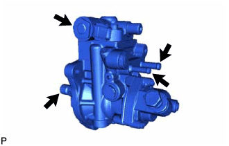
Do not hold the supply pump assembly by the parts indicated by the arrows in the illustration.
-
With SST set, do not turn the crankshaft more than a half rotation.
-
Apply a light coat of engine oil to a new O-ring.
-
Install the O-ring to the supply pump assembly.
-
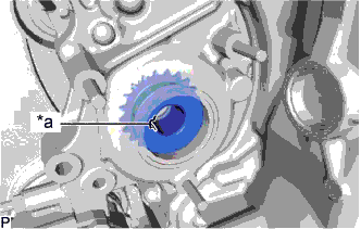
Text in Illustration *a Groove 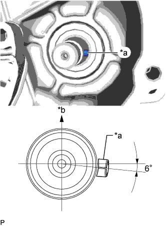
Text in Illustration *a Supply Pump Shaft Key *b Upper Side To insert the supply pump assembly shaft into the supply pump shaft sprocket, it may be necessary to turn the supply pump assembly several degrees so that the spline of the supply pump assembly shaft and groove shown in the illustration are aligned.
Tech Tips
When installing a new supply pump assembly, adjust the supply pump assembly injection pump drive shaft key assignment by turning the supply pump assembly shown in the illustration.
-
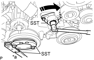
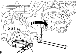
Text in Illustration *a Hold 
Turn Using SST, tighten the supply pump assembly clockwise direction, and then temporarily install the 3 fuel supply pump fixing nuts.
- SST
- 09213-58014 ( 91551-80840 )
- 09330-00021
- 09241-11010
-
Using SST, tighten and insert the supply pump assembly up to the position shown in the illustration and tighten the 3 fuel supply pump fixing nuts.
- Torque:
- 21 N*m { 214 kgf*cm, 15 ft.*lbf }
Tech Tips
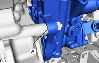
After tightening the part with SST, a gap of 2 to 3 mm in area A shown in the illustration is normal.
-
Install the No. 1 fuel pump bracket with the 2 bolts to the supply pump assembly and cylinder block sub-assembly.
- Torque:
- 21 N*m { 214 kgf*cm, 15 ft.*lbf }
-
Remove SST and the 3 set bolts.
-
Text in Illustration *a Hold Turn Using SST, hold the crankshaft pulley sub-assembly and tighten the set nut.
- SST
- 09213-58014 ( 91551-80840 )
- 09330-00021
- Torque:
- 137 N*m { 1397 kgf*cm, 101 ft.*lbf }
-
-
INSTALL TIMING CHAIN COVER PLATE
-
Install the timing chain cover plate and new gasket with the 3 bolts.
- Torque:
- 10 N*m { 102 kgf*cm, 7 ft.*lbf }
-
-
INSTALL FUEL PUMP MOTOR WIRE
-
Connect the fuel pump motor wire connector and install the fuel pump motor wire.
-
-
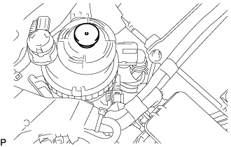
INSTALL FUEL INJECTION PUMP COVER SUB-ASSEMBLY
-
Install the fuel injection pump cover sub-assembly to the supply pump assembly.
-
-
INSTALL NO. 1 FUEL HOSE
-
Install the No. 1 fuel hose to the supply pump assembly and No. 2 fuel pipe, and slide the 2 clamps to secure it.
-
-
INSTALL NO. 2 FUEL HOSE
-
Install the No. 2 fuel hose to the supply pump assembly and No. 3 nozzle leakage pipe assembly, and slide the 2 clamps to secure it.
-
-
INSTALL V-RIBBED BELT TENSIONER ASSEMBLY
-
Install the V-ribbed belt tensioner assembly to the timing chain cover sub-assembly with the 3 bolts.
- Torque:
- 21 N*m { 214 kgf*cm, 15 ft.*lbf }
-
-
INSTALL FAN AND GENERATOR V BELT
-
Установите поликлиновой ремень вентилятора и генератора на каждую деталь.
Tech Tips
При установке поликлиновой ремень вентилятора и генератора устанавливается на опорный ролик № 1 в сборе в последнюю очередь.
-
Повернув натяжитель поликлинового ремня по часовой стрелке, снимите стержень.
-
Убедитесь, что поликлиновой ремень вентилятора и генератора правильно располагается в углублениях шкива.
Note
Проверьте правильность посадки поликлинового ремня вентилятора и генератора на каждом шкиве.
-
-
CONNECT NO. 1 RADIATOR HOSE
-
Connect the No. 1 radiator hose to the water inlet, and slide the clip to secure the hose.
-
-
INSTALL NO. 4 AIR HOSE
-
Install the No. 4 air hose and tighten the 2 hose clamps.
- Torque:
- 6.0 N*m { 61 kgf*cm, 53 in.*lbf }
-
Connect the oil return hose and slide the 2 clips to secure the hose.
-
-
CONNECT NO. 1 AIR HOSE
-
Connect the No. 1 air hose to the No. 1 air tube, and slide the clamp to secure the hose.
-
-
INSTALL INTAKE MANIFOLD
-
CONNECT CABLE TO NEGATIVE BATTERY TERMINAL
Note
When disconnecting the cable, some systems need to be initialized after the cable is reconnected Click here.
-
BLEED AIR FROM FUEL SYSTEM
-
Using the hand pump mounted on the fuel filter cap, bleed air from the fuel system. Continue pumping until the pump resistance increases.
Note
-
The maximum hand pump pumping speed is 2 strokes per second.
-
The hand pump must be pushed with a full stroke during pumping.
-
When the fuel pressure at the supply pump inlet port reaches a saturated pressure, the hand pump resistance increases.
-
If pumping is interrupted during the air bleeding process, fuel in the fuel line may return to the fuel tank. Continue pumping until the hand pump resistance increases.
-
If the hand pump resistance does not increase despite consecutively pumping 200 times or more, there may be a fuel leak between the fuel tank and fuel filter, the hand pump may be malfunctioning, or the vehicle may have run out of fuel.
-
If air bleeding using the hand pump is incomplete, the common rail pressure does not rise to the pressure range necessary for normal use and the engine cannot be started.
-
-
Check if the engine starts.
Note
-
Even if air bleeding using the hand pump has been completed, the starter may need to be cranked for 10 seconds or more to start the engine.
-
Do not crank the engine continuously for more than 20 seconds. The battery may be discharged.
-
Use a fully-charged battery.
-
When the engine can be started, proceed to the next step.
-
If the engine cannot be started, bleed air again using the hand pump until the hand pump resistance increases (refer to the procedures above). Then start the engine.
-
-
Turn the ignition switch off.
-
Connect the GTS to the DLC3.
-
Turn the ignition switch to ON and turn the GTS on.
-
Clear the DTCs Click here.
-
Start the engine.*1
-
Enter the following menus: Powertrain / Engine and ECT / Active Test / Test the Fuel Leak.*2
-
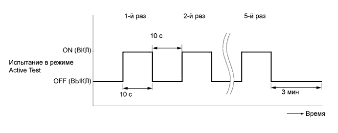
Perform the following test 5 times with on/off intervals of 10 seconds: Active Test / Test the Fuel Leak.*3
-
Allow the engine to idle for 3 minutes or more after performing the Active Test for the 5th time.
Tech Tips
When the Active Test "Test the Fuel Leak" is used to change the pump control mode, the actual fuel pressure inside the common rail drops below the target fuel pressure when the Active Test is off, but this is normal and does not indicate a pump malfunction.
-
Enter the following menus: Powertrain / Engine and ECT /Trouble Codes.
-
Read Current DTCs.
-
Clear the DTCs Click here.
Tech Tips
It is necessary to clear the DTCs as DTC P1604 or P1605 may be stored when air is bled from the fuel system after replacing or repairing fuel system parts.
-
Repeat steps *1 to *3.
-
Enter the following menus: Powertrain / Engine and ECT / Trouble Codes.
-
Read Current DTCs.
OK No DTCs are output.
-
-
INSPECT FOR FUEL LEAK
Note
-
During Active Test mode, the engine speed becomes high and the combustion noise becomes loud, so pay attention.
-
During Active Test mode, the fuel pressure becomes high. Be extremely careful not to expose your eyes, hands, or body to escaping fuel.
Tech Tips
Using the GTS to perform Active Tests allow relays, VSVs, actuators and other items to be operated without removing any parts. This non-intrusive functional inspection can be very useful because intermittent operation may be discovered before parts or wiring is disturbed. Performing Active Tests early in troubleshooting is one way to save diagnostic time. Data List information can be displayed while performing Active Tests.
-
Check that there are no leaks from any part of the fuel system when the engine is stopped. If there is fuel leakage, repair or replace parts as necessary.
-
Start the engine and check that there are no leaks from any part of the fuel system. If there is fuel leakage, repair or replace parts as necessary.
-
Disconnect the return hose from the common rail assembly.
-
Start the engine and check for fuel leaks from the return pipe. If there is fuel leakage, replace the common rail assembly.
-
Perform the Active Test.
-
Connect the GTS to the DLC3.
-
Turn the ignition switch to ON.
-
Turn the GTS on.
-
Enter the following menus: Powertrain / Engine / Active Test / Test the Fuel Leak.
-
If the GTS is not available, fully depress the accelerator pedal quickly. Increase the engine speed to the maximum and maintain that speed for 2 seconds. Repeat this operation several times.
-
Check that there are no leaks from any part of the fuel system.
Tech Tips
A return pipe leakage of less than 10 cc (0.6 cu in.) per minute is acceptable.
If there is fuel leakage, repair or replace parts as necessary.
-
-
Reconnect the return hose to the common rail assembly.
-