ТОПЛИВНАЯ СИСТЕМА СХЕМА СИСТЕМЫ
-
FUEL FLOW DIAGRAM
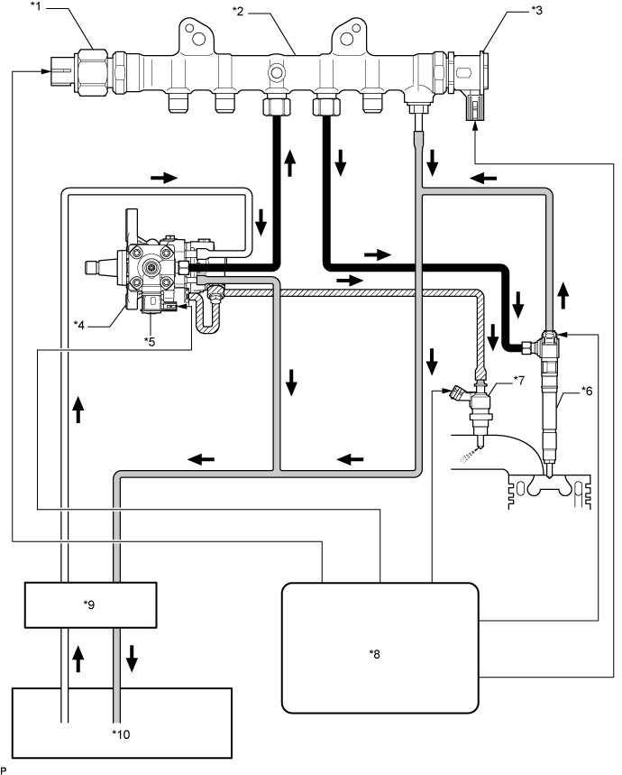
Text in Illustration *1 Fuel Pressure Sensor *2 Common Rail Assembly *3 Pressure Discharge Valve *4 Fuel Supply Pump Assembly *5 Pre-Stroke Control Valve *6 Injector Assembly *7 Exhaust Fuel Addition Injector Assembly *8 ECM *9 Fuel Filter Assembly *10 Fuel Tank Assembly 
High Pressure Fuel Line 
Return Fuel Line 
Suction Fuel Line 
Pressurized Fuel Line -
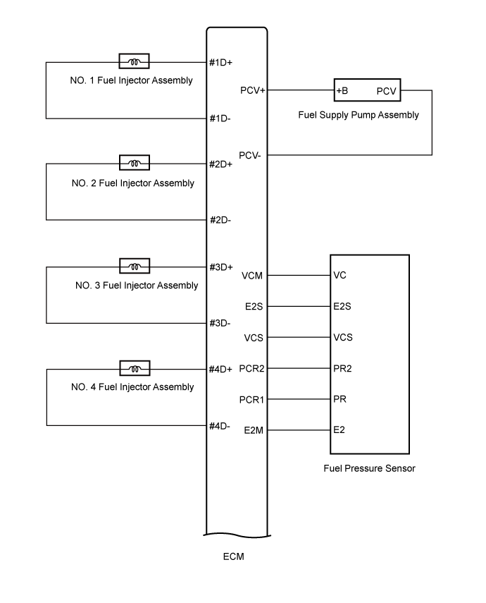
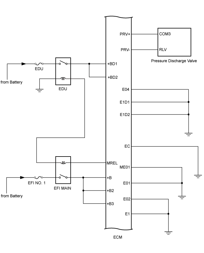
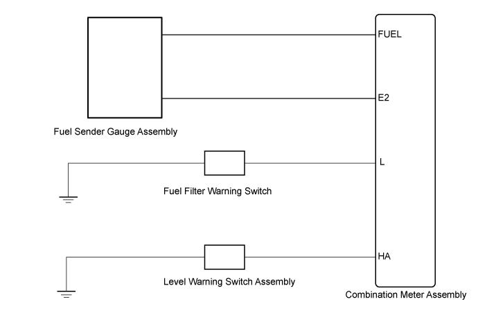
FUEL SYSTEM WIRING DIAGRAM
-
By storing fuel at high pressure, the common rail system provides high pressure fuel injection.
-