As the engine assembly with transaxle is extremely heavy, the engine lifter may suddenly drop if the instructions listed in the repair manual are not followed. Therefore, always follow the instructions listed in the repair manual when performing this procedure.
- Click here
INSTALL ENGINE OIL LEVEL SENSOR
-
Install the engine oil level sensor with the 4 bolts.
7.0 N*m 71 kgf*cm 52 in.*lbf
-
- Click here
INSTALL FRONT NO. 1 ENGINE MOUNTING BRACKET LH
Tip:Perform this procedure only when replacement of the No. 1 engine mounting bracket LH is necessary.
-
Install the front No. 1 engine mounting bracket LH with the 4 bolts to the cylinder block.
51 N*m 520 kgf*cm 38 ft.*lbf
-
- Click here
INSTALL FRONT NO. 1 ENGINE MOUNTING BRACKET RH
Tip:Perform this procedure only when replacement of the No. 1 engine mounting bracket RH is necessary.
-
Install the front No. 1 engine mounting bracket RH with the 4 bolts to the cylinder block.
51 N*m 520 kgf*cm 38 ft.*lbf
-
- Click here
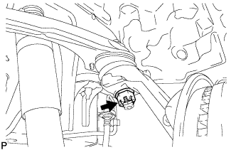
INSTALL ENGINE COOLANT TEMPERATURE SENSOR
-
Install a new gasket onto the engine coolant temperature sensor.
-
Using a 19 mm deep socket wrench, install the engine coolant temperature sensor.
20 N*m 200 kgf*cm 14 ft.*lbf -
Connect the engine coolant temperature sensor connector.
-
- Click here
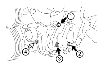
INSTALL KNOCK CONTROL SENSOR
-
Install the knock control sensor with the bolt as shown in the illustration.
20 N*m 204 kgf*cm 15 ft.*lbf Table 1. Text in Illustration *a Front -
Connect the knock control sensor connector.
-
- Click here
INSTALL ENGINE OIL PRESSURE SWITCH ASSEMBLY
-
Apply adhesive to 2 or 3 threads of the engine oil pressure switch assembly.
Adhesive Toyota Genuine Adhesive 1344, Three Bond 1344 or equivalent Note:Do not let adhesive adhere to the oil hole.
-
Install the engine oil pressure switch assembly.
15 N*m 153 kgf*cm 11 ft.*lbf Note:Do not start the engine within 1 hour of installation.
-
- Click here
INSTALL V-RIBBED BELT TENSIONER ASSEMBLY
-
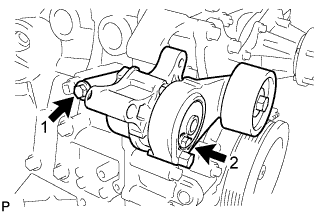
Temporarily install the V-ribbed belt tensioner assembly with the 2 bolts.
Tip:
-
Make sure that the V-ribbed belt tensioner assembly is in contact with the engine block.
-
Check that the bolt holes of the V-ribbed belt tensioner assembly and timing chain cover are aligned.
-
-
Install the V-ribbed belt tensioner assembly by tightening the 2 bolts in the order shown in the illustration.
for bolt 1 40 N*m 408 kgf*cm 30 ft.*lbf for bolt 2 21 N*m 214 kgf*cm 15 ft.*lbf
-
- Click here
INSTALL NO. 1 IDLER PULLEY SUB-ASSEMBLY
-
Install the No. 1 idler pulley sub-assembly, collar and pulley plate with the bolt.
43 N*m 438 kgf*cm 32 ft.*lbf Note:Check that the pulley plate and collar are assembled properly to the No. 1 idler pulley sub-assembly.
-
- Click here
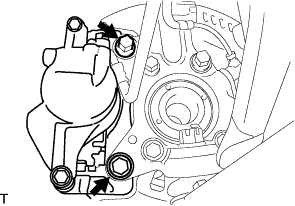
INSTALL NO. 1 COMPRESSOR MOUNTING BRACKET
Note:Install the No. 1 compressor mounting bracket exactly as described in the procedures below to properly secure and prevent damage to the fan and generator V belt.
-
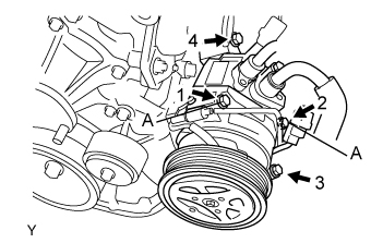
Temporarily install the No. 1 compressor mounting bracket with the 3 bolts.
Tip:Temporarily install the No. 1 compressor mounting bracket with the 3 bolts so that the bracket can be moved by hand.
-
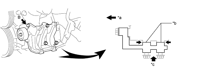
Push the No. 1 compressor mounting bracket toward the cylinder block as shown in the illustration and tighten bolt B.
Table 2. Text in Illustration *a Front *b No Clearance *c Push - - Bolt B 45 N*m 459 kgf*cm 33 ft.*lbf Tip:Make sure there is no clearance between the cylinder block and No. 1 compressor mounting bracket as shown in the illustration.
-
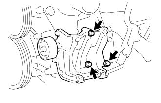
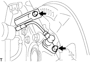
Uniformly tighten the 4 bolts in the order shown in the illustration.
Table 3. Text in Illustration 
Bolt A 
Bolt C Bolt A 45 N*m 459 kgf*cm 33 ft.*lbf Bolt C 25 N*m 255 kgf*cm 18 ft.*lbf
-
- Click here
INSTALL IDLE PULLEY ASSEMBLY
-
Temporarily install the idle pulley assembly with the bolt.
Note:Do not use any tools.
-
Tighten the bolt.
44 N*m 449 kgf*cm 32 ft.*lbf
-
- Click here
INSTALL GENERATOR ASSEMBLY
-
Install the generator assembly with the 3 bolts.
43 N*m 438 kgf*cm 32 ft.*lbf -
Connect the wire harness clamp with the bolt.
-
Connect the wire harness to terminal B with the nut.
9.8 N*m 100 kgf*cm 87 in.*lbf -
Install the terminal cap.
-
Connect the generator connector.
-
- Click here
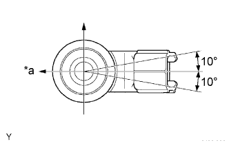
INSTALL THERMOSTAT
-
Install a new gasket to the thermostat.
-
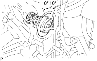
Install the thermostat with the jiggle valve upward.
Tip:The jiggle valve may be set within 10° of either side of the prescribed position.
-
- Click here
INSTALL WATER INLET
-
Install a new gasket and connect the water inlet with the bolt and 2 nuts.
28 N*m 286 kgf*cm 21 ft.*lbf
-
- Click here
INSTALL NO. 1 WATER BY-PASS PIPE
-
Install a new gasket and the No. 1 water by-pass pipe with the 2 nuts and bolt.
18 N*m 178 kgf*cm 13 ft.*lbf
-
- Click here
INSTALL FAN PULLEY
-
Install the fan spacer and fan pulley with the 4 nuts.
25 N*m 255 kgf*cm 18 ft.*lbf
-
- Click here
INSTALL EXHAUST MANIFOLD
-
Install a new gasket and the exhaust manifold with 8 new nuts.
36 N*m 367 kgf*cm 27 ft.*lbf
-
- Click here
INSTALL AIR SWITCHING VALVE ASSEMBLY
-
Install the air switching valve assembly with 2 new nuts.
20 N*m 204 kgf*cm 15 ft.*lbf -
Connect the air switching valve connector.
-
- Click here
INSTALL NO. 4 INTAKE PIPE
-
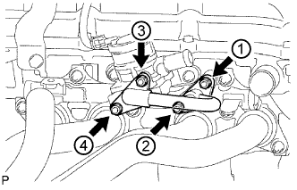
Install 2 new gaskets and the No. 4 intake pipe with 4 new nuts in the order shown in the illustration. Tighten the nuts labeled 1 and 3 to the torque specification again.
20 N*m 204 kgf*cm 15 ft.*lbf -
Check that the nuts are tightened to the torque specification.
Note:Tightening the nuts only once is not enough to tighten them to the torque specification.
-
- Click here
INSTALL NO. 1 EXHAUST MANIFOLD HEAT INSULATOR
-
Install the No. 1 exhaust manifold heat insulator with the 4 bolts.
12 N*m 122 kgf*cm 9 ft.*lbf
-
- Click here
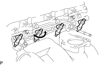
INSTALL FUEL INJECTOR ASSEMBLY
-
Apply a light coat of gasoline or spindle oil to new O-rings and install them to the injector spacers.
Note:Make sure that the O-rings are installed between the parts correctly.
-
Install the 4 injector spacers to the cylinder head sub-assembly.
-
Apply a light coat of gasoline or spindle oil to new O-rings, and then install one onto each fuel injector assembly.
-
Apply a light coat of gasoline or spindle oil to the contact surfaces of the fuel delivery pipe sub-assembly and the O-ring of the fuel injector assembly.
-
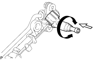
Apply a light coat of gasoline or spindle oil to the O-ring again, and then install the fuel injector assembly into the fuel delivery pipe sub-assembly by turning it right and left.
Table 4. Text in Illustration Turn Push Note:
-
Be careful not to twist the O-ring.
-
After installing the fuel injector assembly, check that it turns smoothly. If not, reinstall it with a new O-ring.
-
-
- Click here
INSTALL FUEL DELIVERY PIPE SUB-ASSEMBLY
-
Install 4 new injector vibration insulators to the cylinder head sub-assembly.
-
Install the 2 No. 1 delivery pipe spacers to the cylinder head sub-assembly.
-
Temporarily install the fuel delivery pipe sub-assembly together with the 4 fuel injector assemblies with the 2 bolts.
Note:
-
Do not drop the fuel injector assembly when installing the fuel delivery pipe sub-assembly.
-
Make sure that the fuel injector assembly turns smoothly.
-
-
Tighten the 2 bolts.
12 N*m 122 kgf*cm 9 ft.*lbf -
Apply a light coat of gasoline or spindle oil to a new O-ring.
-
Install the fuel pressure pulsation damper assembly with the 2 bolts.
8.5 N*m 87 kgf*cm 75 in.*lbf -
Connect the 4 fuel injector connectors.
-
Connect the No. 2 fuel hose to the fuel pressure regulator assembly, and slide the clamp to secure the hose.
-
Connect the vacuum hose to the fuel pressure regulator assembly.
-
- Click here
INSTALL SPARK PLUG
-
Using a 16 mm spark plug wrench, install the 4 spark plugs.
18 N*m 184 kgf*cm 13 ft.*lbf
-
- Click here
INSTALL IGNITION COIL ASSEMBLY
-
Install the ignition coils with the bolts.
9.0 N*m 92 kgf*cm 80 in.*lbf
-
- Click here
INSTALL INTAKE MANIFOLD
-
Install a new gasket onto the intake manifold.
-
Install the intake manifold with the 5 bolts and 2 nuts.
25 N*m 255 kgf*cm 18 ft.*lbf -
Install the bolt and wire harness bracket to the intake manifold.
8.0 N*m 82 kgf*cm 71 in.*lbf -
Connect the vacuum hose to the intake manifold, and slide the clamp to secure the hose.
-
Connect the No. 3 PCV hose to the intake manifold, and slide the clamp to secure the hose.
-
Attach the 2 wire harness clamps to the wire harness bracket.
-
Connect the purge line hose to the vacuum switching valve, and slide the clamp to secure the hose.
-
Connect the vacuum switching valve connector.
-
- Click here
INSTALL THROTTLE WITH MOTOR BODY ASSEMBLY
-
Install a new gasket onto the intake manifold.
Tip: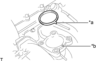
Align the protrusion of the gasket with the groove of the intake manifold.
Table 5. Text in Illustration *a Protrusion *b Groove -
Install the throttle body assembly with the 4 bolts.
9.0 N*m 92 kgf*cm 80 in.*lbf -
Connect the No. 2 water by-pass hose to the throttle body assembly, and slide the clamp to secure the hose.
-
Connect the water by-pass hose to the throttle body assembly, and slide the clamp to secure the hose.
-
Connect the throttle motor connector.
-
- Click here
INSTALL PCV PIPE
-
Install the PCV pipe with the bolt.
18 N*m 184 kgf*cm 13 ft.*lbf
-
- Click here
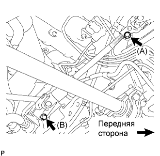
INSTALL ENGINE HANGER
-
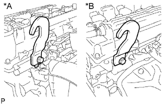
Установите 2 крюка для вывешивания двигателя и закрепите их 2 болтами.
42 Н*м 428 кгс*см 31 фунт-сила-фут Table 6. Обозначения на рисунке *A Левая сторона *B Правая сторона Tip:Крюки для вывешивания двигателя 12281-75040 Болт 91552-A1020 Note:Для крепления 2 крюков для вывешивания двигателя используйте 2 новых болта.
-
- Click here
REMOVE ENGINE FROM ENGINE STAND
Note:
-
Pay attention to the angle of the sling device as the engine assembly or engine hangers may be damaged or deformed if the angle is incorrect.
-
With the exception of installing the engine assembly to an engine stand or removing the engine assembly from an engine stand, do not perform any work on the engine while it is suspended, as doing so is dangerous.
-
Attach a sling device and hang the engine with a chain block.
-
Lift the engine and remove it from the engine stand.
-
- Click here
FIX ENGINE ASSEMBLY
-
С помощью деревянных брусков или приспособлений для подъемника платформенного типа установите двигатель на плоскую поверхность.
Note:
-
Поместите деревянные бруски или приспособления для подъемника платформенного типа так, чтобы двигатель располагался без перекоса.
-
Во избежание деформации поддона картера не устанавливайте какие-либо приспособления на поддон картера двигателя или трансмиссию.
-
Выполните эту операцию, поддерживая двигатель в сборе с помощью стропы и цепного блока.
-
-
- Click here
INSTALL ENGINE WIRE
-
Install the engine wire to the engine assembly.
-
- Click here
INSTALL FRONT SUSPENSION CROSSMEMBER SUB-ASSEMBLY
-
Install the engine assembly to the crossmember sub-assembly.
-
Connect the engine mounting insulator with the 4 bolts.
55 N*m 561 kgf*cm 41 ft.*lbf
-
- Click here
INSTALL REAR END PLATE
-
Install the rear end plate with the bolt.
18 N*m 184 kgf*cm 13 ft.*lbf -
Connect the No. 1 water by-pass pipe to the rear end plate with the bolt.
18 N*m 178 kgf*cm 13 ft.*lbf
-
- Click here
INSTALL DRIVE PLATE AND RING GEAR SUB-ASSEMBLY
-
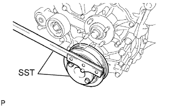
Using SST, hold the crankshaft.
09213-54015 91651-60855 09330-00021 -
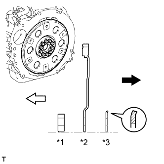
Install the front drive plate spacer, drive plate and ring gear sub-assembly and rear drive plate spacer to the crankshaft.
Table 7. Text in Illustration *1 Front Drive Plate Spacer (Reversible) *2 Drive Plate and Ring Gear Sub-assembly *3 Rear Drive Plate Spacer Transmission Side Engine Side Tip:
-
The front drive plate spacer is reversible.
-
As the rear drive plate spacer and drive plate and ring gear sub-assembly are not reversible, be sure to install it so that it is facing in the direction shown in the illustration.
-
-
Clean the bolts and bolt holes.
-
Apply adhesive to 2 or 3 threads at the end of each of the 10 bolts.
Adhesive Toyota Genuine Adhesive 1324, Three Bond 1324 or equivalent -
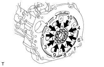
Install and uniformly tighten the 10 bolts in several steps in the sequence shown in the illustration.
74 N*m 755 kgf*cm 55 ft.*lbf Note:Do not start the engine for at least an hour after installing the drive plate and ring gear sub-assembly.
-
- Click here
INSTALL AUTOMATIC TRANSMISSION ASSEMBLY
- Click here
INSTALL STARTER ASSEMBLY
-
Install the starter assembly with the 2 bolts.
37 N*m 377 kgf*cm 27 ft.*lbf -
Connect the wire harness with the nut.
9.8 N*m 100 kgf*cm 87 in.*lbf -
Install the terminal cap.
-
Connect the starter connector.
-
Connect the wire harness with the bolt.
25 N*m 250 kgf*cm 18 ft.*lbf -
Install the wire harness bracket with the bolt.
25 N*m 250 kgf*cm 18 ft.*lbf -
Attach the wire harness clamp to the wire harness bracket.
-
- Click here
INSTALL ENGINE ASSEMBLY WITH TRANSMISSION
-
Place the engine on an engine lifter.
Tip:Place the engine on wooden blocks or equivalent so that the engine is level.
-
Operate the engine lifter and install the engine to the vehicle.
CAUTION:Do not raise the engine more than necessary. If the engine is raised excessively, the vehicle may also be lifted up.
Note:
-
Make sure that the engine is clear of all wiring and hoses.
-
While raising the engine into the vehicle, do not allow it to contact the vehicle.
-
-
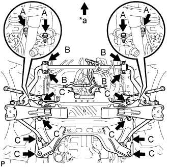
Install the stabilizer bracket and 16 bolts of the front suspension crossmember.
for bolt A 39 N*m 398 kgf*cm 29 ft.*lbf for bolt B 36 N*m 367 kgf*cm 27 ft.*lbf for bolt C 150 N*m 1530 kgf*cm 111 ft.*lbf Table 8. Text in Illustration *a Front Side -
Connect the rear engine mount.
98 N*m 999 kgf*cm 72 ft.*lbf Note:Be sure to tighten the nut side.
-
Remove the engine lifter slowly.
-
Remove the 2 bolts and 2 engine hangers.
-
- Click here
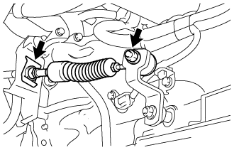
CONNECT STEERING TORQUE SHAFT ASSEMBLY
-
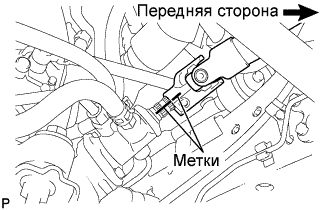
Совместите метки на крутящем валу рулевого управления в сборе и тяге рулевого управления с усилителем в сборе.
-
Вверните болт (B) и затяните 2 болта.
35 Н*м 360 кгс*см 26 фунт-сила-футов
-
- Click here
CONNECT OIL COOLER HOSE
-
Connect the inlet oil cooler hose and outlet oil cooler hose to the oil cooler tube, and slide the 2 clamps to secure the hose.
-
- Click here
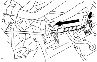
CONNECT TRANSMISSION CONTROL CABLE ASSEMBLY
-
Connect the transmission control shift cable assembly with a new clip and nut.
15 N*m 148 kgf*cm 11 ft.*lbf
-
- Click here
INSTALL TRANSMISSION OIL FILLER TUBE SUB-ASSEMBLY
-
Coat a new O-ring with ATF, and install it to the transmission oil filler tube sub-assembly.
-
Install the transmission oil filler tube sub-assembly with the 2 bolts.
12 N*m 122 kgf*cm 9 ft.*lbf -
Install the oil level dipstick.
-
- Click here
CONNECT FRONT SHOCK ABSORBER ASSEMBLY LH
- Click here
CONNECT FRONT SHOCK ABSORBER ASSEMBLY RH
Tip:Use the same procedure described for the LH side.
- Click here
CONNECT FRONT SUSPENSION SUB-ASSEMBLY UPPER LH
-
Подсоедините верхний рычаг передней подвески к поворотному кулаку и закрепите гайкой.
113 Н*м 1 150 кгс*см 83 фунт-сила-фута -
Установите новый шплинт.
Note:
-
Если отверстия под шплинт не совпадают, затяните гайку на угол до 60°.
-
Старайтесь не повредить пыльник шарового шарнира.
-
-
- Click here
CONNECT FRONT SUSPENSION SUB-ASSEMBLY UPPER RH
Tip:Use the same procedure described for the LH side.
- Click here
INSTALL FRONT DISC BRAKE CALIPER ASSEMBLY LH
-
Установите суппорт тормоза в сборе на поворотный кулак и закрепите 2 болтами.
123 Н*м 1 250 кгс*см 91 фунт-сила-фут
-
- Click here
INSTALL FRONT DISC BRAKE CALIPER ASSEMBLY RH
Tip:Use the same procedure described for the LH side.
- Click here
INSTALL FRONT SPEED SENSOR LH
-
Установите датчик частоты вращения на поворотный кулак и закрепите его 2 болтами.
8,5 Н*м 87 кгс*см 75 фунт-сила-дюймов Note:
-
Не допускайте налипания на датчик частоты вращения посторонних частиц.
-
Будьте осторожны, чтобы не повредить датчик частоты вращения.
-
Не допускайте перекручивания провода датчика частоты вращения при установке.
-
-
- Click here
INSTALL FRONT SPEED SENSOR RH
Tip:Use the same procedure described for the LH side.
- Click here
INSTALL PROPELLER SHAFT ASSEMBLY
-
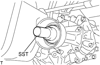
Снимите SST с удлинителя картера трансмиссии.
-
Установите карданный вал в сборе в удлинитель картера трансмиссии.
-
Совместите метки на фланце карданного вала и фланце дифференциала.
-
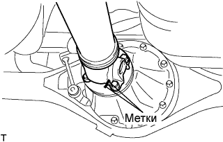
Закрепите карданный вал в сборе с помощью 4 гаек, 4 болтов и 4 шайб.
74 Н*м 755 кгс*см 54 фунт-сила-фута
-
- Click here
INSTALL FRONT EXHAUST PIPE ASSEMBLY
-
Установите пружину сжатия.
-
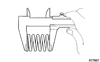
С помощью штангенциркуля измерьте длину пружин в свободном состоянии.
Минимально допустимая длина 40,5 мм (1,59 дюйма) Tip:Если длина в свободном состоянии меньше минимально допустимой, замените пружину сжатия.
-
-
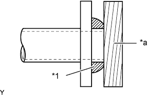
Установите прокладку.
Table 9. Обозначения на рисунке *1 Прокладка *a Деревянный брусок
-
Вручную полностью вставьте 2 новые прокладки в выпускной коллектор и приемную трубу.
-
Наденьте прокладку на выпускной коллектор и приемную трубу в сборе с помощью деревянного бруска, равномерно распределяя удары.
Note:
-
Правильно выберите направление установки прокладки.
-
Повторное использование прокладок запрещено.
-
Действуйте осторожно, чтобы не повредить прокладку.
-
Чтобы обеспечить хорошее уплотнение, не насаживайте прокладку на выпускной коллектор с помощью приемной трубы.
-
Чтобы обеспечить хорошее уплотнение, не насаживайте прокладку на приемную трубу с помощью задней выпускной трубы.
-
-
-
Подсоедините опору выпускной трубы № 4, чтобы установить приемную трубу в сборе.
-
Временно закрепите 4 пружины сжатия и наживите 4 болта на приемной трубе в сборе.
-
Затяните 4 болта.
43 Н*м 438 кгс*см 32 фунт-сила-фута Note:После установки убедитесь, что зазор между фланцами выпускного коллектора, задней выпускной трубы и приемной трубы одинаков по всему периметру.
-
- Click here
CONNECT ENGINE WIRE
-
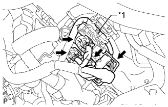
Install the nut and connect the 4 connectors as shown in the illustration.
Table 10. Text in Illustration *1 Nut -
Connect the starter connector (Click here).
-
Connect the generator connector (Click here).
-
Connect the clamps of the engine wire and ground cable.
-
Connect the connectors of the ECM.
-
Connect the wire harness support of the ECM.
-
- Click here
INSTALL COMPRESSOR AND MAGNETIC CLUTCH
-
Temporarily install the bolt A to connect the compressor and magnetic clutch.
-
Connect the compressor and magnetic clutch completely by tightening the 4 bolts in the order shown in the illustration.
25 N*m 250 kgf*cm 18 ft.*lbf Note:In order to prevent misalignment, which causes belt rattle, tightening of the bolts must be performed in the order shown.
-
Connect the compressor and magnetic clutch connector.
-
- Click here
INSTALL ENGINE OIL LEVEL DIPSTICK GUIDE
-
Install a new O-ring and the engine oil level dipstick guide with the bolt to the front No. 1 engine mounting bracket LH.
20 N*m 204 kgf*cm 15 ft.*lbf
-
- Click here
INSTALL ENGINE OIL LEVEL DIPSTICK
- Click here
CONNECT VANE PUMP ASSEMBLY
-
Connect the vane pump assembly with the 2 bolts.
21 N*m 214 kgf*cm 15 ft.*lbf -
Connect the oil pressure switch connector.
-
- Click here
CONNECT NO. 2 FUEL HOSE
-
Connect the No. 2 fuel hose to the fuel delivery pipe sub-assembly (Click here).
-
- Click here
CONNECT NO. 1 FUEL HOSE
-
Connect the No. 1 fuel hose to the fuel pressure pulsation damper assembly (Click here).
-
- Click here
CONNECT NO. 5 AIR HOSE
-
Connect the No. 5 air hose to the air switching valve assembly, and slide the clamp to secure the hose.
-
- Click here
INSTALL INTAKE AIR CONNECTOR
-
Temporarily install the intake air connector to the throttle body assembly.
-
Connect the vacuum hose to the intake air connector.
-
Connect the No. 2 PCV hose to the cylinder head cover sub-assembly, and slide the clamp to secure the hose.
-
Install the intake air connector with the 2 bolts.
8.0 N*m 82 kgf*cm 71 in.*lbf -
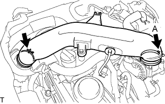
Tighten the 2 hose clamps.
for clamp A 5.0 N*m 51 kgf*cm 44 in.*lbf
-
- Click here
CONNECT UNION TO CONNECTOR TUBE HOSE
-
Connect the union to connector tube hose to the intake manifold, and slide the clamp to secure the hose.
-
- Click here
CONNECT FUEL VAPOR FEED HOSE ASSEMBLY
-
Connect the fuel vapor feed hose assembly to the purge VSV, and slide the clamp to secure the hose.
-
- Click here
CONNECT OUTLET HEATER WATER HOSE B
-
Connect the outlet heater water hose B to the heater unit, and slide the clamp to secure the hose.
-
- Click here
CONNECT INLET HEATER WATER HOSE A
-
Connect the inlet heater water hose A to the heater unit, and slide the clamp to secure the hose.
-
- Click here
CONNECT NO. 2 RADIATOR HOSE
-
Connect the No. 2 radiator hose to the No. 1 radiator pipe, and slide the clamp to secure the hose.
-
- Click here
CONNECT NO. 4 RADIATOR HOSE
-
Connect the No. 4 radiator hose to the engine, and slide the clamp to secure the hose.
-
- Click here
INSTALL FAN AND GENERATOR V BELT
-
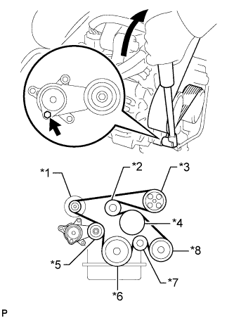
Установите поликлиновой ремень вентилятора и генератора на все шкивы, кроме шкива натяжителя поликлинового ремня.
Table 11. Обозначения на рисунке *1 Генератор *2 Опорный шкив № 1 *3 Лопастной насос *4 Шкив вентилятора *5 Шкив натяжителя *6 Шкив коленчатого вала *7 Опорный ролик *8 Компрессор системы кондиционирования -
С помощью шестигранника, указанного на рисунке стрелкой, сдвиньте шкив натяжителя вниз, а затем установите поликлиновой ремень вентилятора и генератора на шкив натяжителя.
Note:
-
Поликлиновой ремень вентилятора и генератора должен быть обращен к шкиву натяжителя тыльной стороной.
-
Проверьте правильность посадки поликлинового ремня вентилятора и генератора на шкиве и ролике.
-
-
- Click here
INSPECT FAN AND GENERATOR V BELT
-
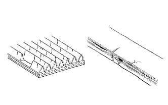
Убедитесь в отсутствии износа, трещин и других признаков повреждения.
При обнаружении следующих дефектов замените вентилятор и поликлиновой ремень генератора.
-
Ремень имеет трещины.
-
Ремень изношен до такой степени, что обнажились волокна
-
Отсутствуют элементы ребер ремня.
-
-
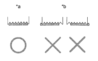
Убедитесь в том, что приводной ремень правильно располагается в углублениях шкива.
Table 12. Обозначения на рисунке *a ПРАВИЛЬНО *b НЕПРАВИЛЬНО Tip:Рукой проверьте, не выскользнул ли ремень из канавок в нижней части шкива. Если ремень выскользнул, замените вентилятор и поликлиновой ремень генератора. Надлежащим образом установите новый вентилятор и поликлиновой ремень генератора.
-
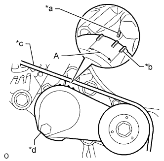
Убедитесь, что индикаторная метка натяжителя находится в диапазоне A, как показано на рисунке.
Table 13. Обозначения на рисунке *a Метка со стороны кронштейна *b Метка со стороны рычага *c Поликлиновой ремень вентилятора и генератора *d Натяжитель поликлинового ремня в сборе Если метка находится вне зоны A, замените поликлиновой ремень вентилятора и генератора.
Tip:Если установлен новый ремень, то убедитесь в том, что указатель натяжителя находится в диапазоне A.
-
- Click here
INSTALL ENGINE SERVICE HOLE SUB COVER SUB-ASSEMBLY
-
Установите крышку технологического отверстия двигателя и закрепите 5 болтами.
13 Н*м 133 кгс*см 10 фунт-сила-футов
-
- Click here
INSTALL FRONT DOOR SCUFF PLATE
- Click here
INSTALL FRONT SEAT ASSEMBLY RH
- Click here
CONNECT CABLE TO NEGATIVE BATTERY TERMINAL
Note:When disconnecting the cable, some systems need to be initialized after the cable is reconnected (Click here).
- Click here
ADD ENGINE OIL
-
Add new engine oil.
Standard Oil Grade Oil Grade Oil Viscosity (SAE) API grade SL "energy-conserving", SM "energy-conserving", SN "resource-conserving" or ILSAC multigrade engine oil
-
0W-20
-
5W-20
-
5W-30
-
10W-30
API grade SL, SM or SN multigrade engine oil
-
15W-40
-
20W-50
Standard Capacity Item Capacity Drain and refill without oil filter change 5.0 liters (5.3 US qts, 4.4 Imp. qts) Drain and refill with oil filter change 5.5 liters (5.8 US qts, 4.8 Imp. qts) Dry fill 6.0 liters (6.3 US qts, 5.3 Imp. qts) -
-
Install the oil filler cap.
-
- Click here
ADD ENGINE COOLANT
-
Tighten the radiator drain cock plug by hand.
-
Tighten the cylinder block water drain cock plug.
13 N*m 130 kgf*cm 9 ft.*lbf -
Fill the radiator reservoir assembly with engine coolant to the top of the inlet.
Standard Capacity 11.2 liters (11.8 US qts, 9.9 Imp. qts) Note:Never use water as a substitute for engine coolant.
Tip:TOYOTA vehicles are filled with TOYOTA SLLC at the factory. In order to avoid damage to the engine cooling system and other technical problems, only use TOYOTA SLLC or similar high quality ethylene glycol based non-silicate, non-amine, non-nitrite, non-borate coolant with long-life hybrid organic acid technology (coolant with long-life hybrid organic acid technology is a combination of low phosphates and organic acids).
-
Remove the 2-way that is located near the throttle body assembly.
-
When air is bleed and the engine coolant drains out, install the 2-way.
-
Add coolant through the radiator reservoir assembly filler opening until the coolant reaches the B line and install the radiator reservoir cap sub-assembly. [*1]
-
Warm up the engine until the thermostat opens. While the thermostat is open, circulate the coolant for several minutes. [*2]
CAUTION:
-
Wear protective gloves.
-
Be careful as the radiator hoses are hot.
-
Keep your hands away from the radiator fans.
Note:
-
Immediately after starting the engine, if the radiator reservoir assembly does not have any engine coolant, perform the following: 1) stop the engine, 2) wait until the engine coolant has cooled down, and 3) add engine coolant.
-
Do not start the engine when there is no engine coolant in the radiator reservoir assembly.
-
Make sure that the needle does not show an abnormally high temperature.
-
If there is not enough engine coolant, the engine may overheat.
Tip:
-
Press the No. 2 and No. 3 radiator hoses several times by hand, and then check the level of the engine coolant.
-
The thermostat open timing can be confirmed by pressing the No. 3 radiator hose by hand, and checking when the engine coolant starts to flow inside the hose.
-
-
Stop the engine, and wait until the engine coolant cools down to ambient temperature. [*3]
-
Check the engine coolant level in the radiator reservoir assembly. [*4]
Tip:
-
If the engine coolant level is below the LOW line, repeat steps *1 through *4.
-
If the engine coolant level is above the FULL line, drain engine coolant until the engine coolant level is between the FULL and LOW line.
-
-
- Click here
INSPECT FOR FUEL LEAK
-
Check that there are no fuel leaks after performing maintenance anywhere on the fuel system.
If there are fuel leaks, repair or replace parts as necessary.
-
- Click here
INSPECT FOR OIL LEAK
-
Start the engine. Make sure that there are no oil leaks from the areas that were worked on.
-
- Click here
CHECK AUTOMATIC TRANSMISSION FLUID LEVEL
Tip:
-
Drive the vehicle so that the engine and transmission are at the normal operating temperature.
ATF temperature 70 to 80°C (158 to 176°F) -
The ATF temperature can be checked with the intelligent tester.
Enter the following menus: Powertrain / Engine and ECT / Data List / A/T Oil Temperature 3.
-
Park the vehicle on a level surface and set the parking brake.
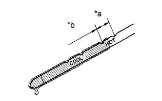
Table 14. Text in Illustration *a OK *b Add -
With the engine idling and the brake pedal depressed, move the shift lever to all positions from P to L, and then return it to P.
-
Pull out the dipstick and wipe it clean.
-
Fully push the dipstick back into the pipe.
-
Pull the dipstick out and check that the fluid level is in the HOT range.
If there are leaks, it is necessary to repair or replace O-rings, seal packing, oil seals, plugs or other parts.
-
- Click here
INSPECT FOR COOLANT LEAKS
CAUTION:Не снимайте пробку расширительного бачка радиатора, пока двигатель и радиатор не остынут. Выброс горячей охлаждающей жидкости и пара под давлением может стать причиной серьезных ожогов.
-
Снимите пробку расширительного бачка радиатора.
-
Заполните расширительный бачок радиатора охлаждающей жидкостью, а затем подсоедините приспособление для опрессовки системы охлаждения и проверки пробки радиатора.
-
Прогрейте двигатель.
-
С помощью приспособления для опрессовки системы охлаждения и проверки пробки радиатора увеличьте давление в радиаторе до 137 кПа (1,4 кгс/см2, 20 фунтов на кв. дюйм) и убедитесь, что давление не падает.
Если давление снижается, проверьте на наличие утечек шланги, радиатор в сборе и насос системы охлаждения двигателя в сборе.
Если нет следов или признаков утечки внешней охлаждающей жидкости, проверьте сердцевину отопителя, блок цилиндров и головку блока цилиндров.
-
Установите пробку расширительного бачка радиатора.
-
- Click here
ADJUST SHIFT LEVER POSITION
-
Remove a clip, nut, and disconnect between the control shaft lever to transmission control cable assembly from the control shaft lever and transmission control cable bracket No. 1.
-
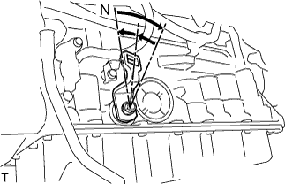
Turn the control shaft lever until stop to a clockwise direction, return the control shaft lever 2 notches to N position.
-
Set the shift lever to N position while holding the shift lever lightly toward the R position side and install it.
15 N*m 150 kgf*cm 11 ft.*lbf -
Inspect the operation condition and work.
-
- Click here
INSPECT SHIFT LEVER POSITION
-
When shifting from P position only with ignition switch ON and depress the break pedal.
-
Make sure that the shifting lever moves smoothly and can be moderately operated.
-
When starting engine, make sure that the vehicle moves forward when shifting from N to D position and moves reward when shifting R position.
-
- Click here
INSPECT FOR EXHAUST GAS LEAK
- Click here
ADJUST FRONT WHEEL ALIGNMENT
- Click here
INSTALL NO. 1 ENGINE UNDER COVER
-
Install the No. 1 engine under cover with the 4 bolts.
13 N*m 133 kgf*cm 10 ft.*lbf
-
- Click here
INSPECT IGNITION TIMING
-
Прогрейте и выключите двигатель.
Note:У прогретого двигателя температура охлаждающей жидкости должна превышать 80°C (176°F), температура моторного масла – 60°C (140°F), а частота вращения коленчатого вала должна быть стабильной.
-
Если используется портативный диагностический прибор:
-
Подсоедините портативный диагностический прибор к DLC3.
-
Запустите двигатель и оставьте его работать на холостом ходу.
-
Включите главный выключатель портативного диагностического прибора.
-
Войдите в следующие меню:
Powertrain / Engine and ECT / Data List / IGN Advance
Номинальный угол опережения зажигания 5-15° до верхней мертвой точки на холостом ходу Note:При проверке угла опережения зажигания трансмиссия должна быть установлена в нейтральное положение или положение парковки.
Tip:Более подробная информация приведена в руководстве по эксплуатации портативного диагностического прибора.
-
-
Если портативный диагностический прибор не используется:
-
Подсоедините щуп стробоскопа к проводу разъема катушки зажигания для цилиндра № 4.
Note:
-
Используйте стробоскоп, который определяет первые сигналы.
-
По окончании проверки обязательно обмотайте жгут проводов лентой.
-
-
Запустите двигатель и оставьте его работать на холостом ходу.
-
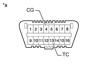
С помощью SST замкнуть контакты 13 (TC) и 4 (CG) разъема DLC3.
09843-18040 Table 15. Обозначения на рисунке *a Вид спереди разъема DLC3 Note:
-
Проверьте номера контактов перед их соединением. Подключение к ненадлежащим контактам может привести к поломке двигателя.
-
При проверке угла опережения зажигания трансмиссия должна быть установлена в нейтральное положение или положение парковки.
Tip:
-
-
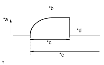
После соединения контактов (TC и CG) частота вращения коленчатого вала двигателя становится равной примерно 1000-1500 об/мин в течение 5 с, а затем возвращается к значению холостого хода. Это обусловлено тем, что ECM проверяет правильность работы системы регулировки частоты вращения холостого хода (ISC).
-
Угол опережения зажигания следует проверять после восстановления частоты вращения холостого хода.
Table 16. Обозначения на рисунке *a Частота вращения коленчатого вала двигателя *b Приблизительно 1000 - 1500 об/мин *c 5 с *d Частота вращения коленчатого вала двигателя на холостом ходу *e Соедините контакты TC и CG -
-
Проверьте угол опережения зажигания.
Номинальный угол опережения зажигания 3 - 7° до верхней мертвой точки на холостом ходу -
Отсоедините контакты 13 (TC) и 4 (CG) DLC3.
-
Проверьте угол опережения зажигания.
Номинальный угол опережения зажигания 5-15° до верхней мертвой точки на холостом ходу -
Убедитесь в том, что угол опережения зажигания возрастает сразу после увеличения частоты вращения коленчатого вала двигателя.
-
Выключите зажигание.
-
Отключите стробоскоп.
-
-
- Click here
INSPECT ENGINE IDLE SPEED
-
Прогрейте и выключите двигатель.
-
Если используется портативный диагностический прибор:
-
Подсоедините портативный диагностический прибор к DLC3.
Tip:Более подробная информация приведена в руководстве по эксплуатации портативного диагностического прибора.
-
Запустите двигатель и оставьте его работать на холостом ходу.
-
Включите главный выключатель портативного диагностического прибора.
-
Войдите в следующие меню:
Powertrain / Engine and ECT /Data List / Engine SPD.
Частота вращения коленчатого вала на холостом ходу 650 - 750 об/мин Note:
-
При проверке работы на холостом ходу трансмиссия должна быть установлена в нейтральное положение.
-
Прежде чем подключать портативный диагностический прибор, выключите все вспомогательное оборудование и систему кондиционирования.
-
-
Выключите зажигание.
-
Отсоедините портативный диагностический прибор от DLC3.
-
-
Если портативный диагностический прибор не используется:
-
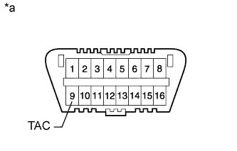
Закрепите SST на контакте 9 (TAC) DLC3, а затем подсоедините тахометр.
09843-18030 Table 17. Обозначения на рисунке *a Вид спереди разъема DLC3 Note:Проверьте номера контактов перед их соединением. Подключение к ненадлежащим контактам может привести к поломке двигателя.
-
Запустите двигатель и оставьте его работать на холостом ходу.
-
Проверьте частоту оборотов холостого хода двигателя.
Частота вращения коленчатого вала на холостом ходу 650 - 750 об/мин -
Выключите зажигание.
-
Отсоедините тахометр.
-
Отсоедините SST от контакта 9 (TAC).
-
-
- Click here
INSPECT CO/HC
-
Запустите и прогрейте двигатель.
-
Запустите двигатель на оборотах 2500 об/мин и дайте ему поработать, по крайней мере, в течение 180 секунд.
-
Вставьте пробник газоанализатора для определения содержания CO/CH не менее, чем на 40 см (1,31 фута) в выхлопную трубу, когда двигатель работает на холостом ходу.
-
Сразу же проверьте концентрацию CO/CH на холостом ходу и на частоте 2500 об/мин.
Tip:
-
При проверке в двух режимах (холостой ход и 2500 об/мин) порядок выполнения измерений определяется применимыми местными нормативными документами.
-
Если концентрация CO/CH не соответствует нормам, произведите диагностику в описанном ниже порядке.
-
-
Если концентрация CO/CH не соответствует указанным значениям, выполните поиск неисправности и устраните ее в порядке, указанном ниже.
-
Проверьте работу датчика состава топливовоздушной смеси (см. стр.Click here) и подогреваемого кислородного датчика (см. стр.Click here).
-
В таблице ниже перечислены возможные неисправности. Проведите проверку и при необходимости устраните причины неисправности.
CO CH Неисправности Причины Нормальное состояние Высокая Неравномерный холостой ход
-
Неисправности в системе зажигания:
-
-
Неправильно отрегулирован угол опережения зажигания
-
Неисправность свечи или замыкание на массу провода свечи зажигания или неправильный зазор между электродами свечи зажигания
-
-
Неправильный зазор в приводе клапанов
-
Негерметичность впускных и выпускных клапанов
-
Утечка из цилиндров
Низкая Высокая Неравномерный холостой ход
(Колебания значения СH)
-
Негерметичность вакуумной системы:
-
-
Шланги системы принудительной вентиляции картера
-
Впускной коллектор
-
Корпус дроссельной заслонки
-
Трубопровод усилителя тормозной системы
-
-
Пропуски зажигания вследствие чрезмерного обеднения смеси
Высокая Высокая Неравномерный холостой ход
(Из выпускной трубы идет черный дым)
-
Засорение воздушного фильтра
-
Засорение клапана принудительной вентиляции картера
-
Неисправна система SFI:
-
-
Неисправен регулятор давления
-
Неисправность датчика температуры охлаждающей жидкости
-
Неисправен массовый расходомер воздуха
-
Неисправен ECM
-
Неисправность форсунок
-
Неисправен корпус дроссельной заслонки
-
-
-
-
- Click here
CHECK FUNCTION OF THROTTLE BODY
Note:
-
Be sure to perform this procedure after reassembling the throttle body assembly or removing and reinstalling any throttle body component.
-
Perform the following procedure after replacing the ECM, throttle body assembly or any throttle body components. The following procedure should also be performed if the throttle body is cleaned.
-
Be sure to perform this procedure after reconnecting the battery cable or replacing the ECM.
-
Disconnect the EFI No. 2 fuse and ETCS fuse at the same time. Wait at least 60 seconds and reconnect the fuses.
-
Turn the ignition switch to ON without operating the accelerator pedal.
Note:If the accelerator pedal is operated, perform the above steps again.
-
Connect the intelligent tester to the DLC3 and clear the DTCs (Click here).
-
Start the engine and check that the MIL is not illuminated. After the engine is warmed up, check that the idle speed is within the specified range when the A/C is switched off.
Standard Condition Engine Idle Speed A/C switched off 650 to 750 rpm Note:
-
Be sure to perform this step with all accessories off.
-
Make sure that the shift lever is in N or P.
-
-
Enter the following menus: Powertrain / Engine and ECT / Data List / All Data / Throttle Sensor Position. Fully depress the accelerator pedal and check that the value is 60% or more.
-
Perform a road test and confirm that there are no abnormalities.
-
- Click here
INSPECT ABS SENSOR SIGNAL
- Click here
PERFORM INITIALIZATION