РАСПРЕДВАЛ СНЯТИЕ

-
REMOVE FRONT SEAT ASSEMBLY RH
-
REMOVE FRONT DOOR SCUFF PLATE RH
-
REMOVE ENGINE SERVICE HOLE SUB COVER SUB-ASSEMBLY
-
Заверните коврик, выверните 5 болтов и снимите дополнительную крышку технологического отверстия двигателя.
-
-
REMOVE FAN AND GENERATOR V BELT
-
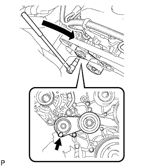
С помощью шестигранника, указанного на рисунке стрелкой, сдвиньте шкив натяжителя вниз, уменьшив тем самым натяжение поликлинового ремня вентилятора и генератора. Затем снимите поликлиновой ремень вентилятора и генератора.
Note
При снятии поликлинового ремня вентилятора и генератора не используйте болт опорного ролика.
Tech Tips
После снятия поликлинового ремня вентилятора и генератора переместите натяжитель вверх, насколько это возможно.
-
-
REMOVE AIR PRESSURE SENSOR
-
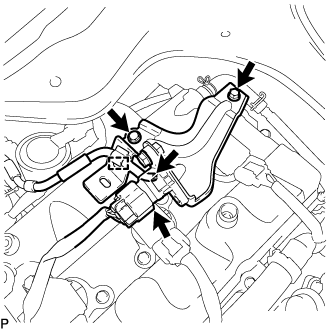
Disconnect the air pressure sensor connector.
-
Disconnect the vacuum hose.
-
Detach the wire harness clamp.
-
Remove the 2 bolts and air pressure sensor together with the bracket.
-
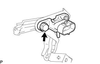
Remove the bolt and air pressure sensor.
-
-
REMOVE INTAKE AIR CONNECTOR
-
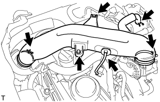
Сдвиньте хомут и отсоедините шланг системы принудительной вентиляции картера № 2 от крышки головки блока цилиндров в сборе.
-
Отсоедините вакуумный шланг от патрубка подачи воздуха.
-
Ослабьте 2 хомута шланга.
-
Выверните 2 болта и снимите соединитель впуска воздуха.
-
-
REMOVE IGNITION COIL ASSEMBLY
-
Выверните 4 болта и снимите 4 катушки зажигания.
-
-
REMOVE CYLINDER HEAD COVER SUB-ASSEMBLY
-
Сдвиньте хомут и отсоедините шланг системы принудительной вентиляции картера от клапана системы принудительной вентиляции картера.
-
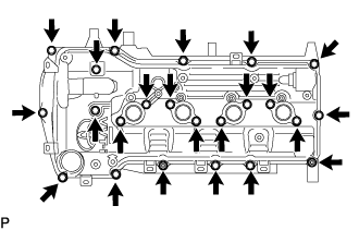
Выверните 21 болт, отверните 2 гайки с 2 плоскими шайбами и 2 уплотнительными шайбами и снимите крышку головки блока цилиндров.
-
Снимите прокладку с крышки головки блока цилиндров в сборе.
-
Снимите прокладку масляного отверстия крышки подшипника распредвала № 1 c распорной втулки крышки головки блока цилиндров.
-
-
REMOVE CYLINDER HEAD COVER CONNECTOR SUB-ASSEMBLY
-
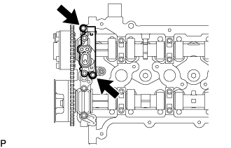
Выверните 2 болта и снимите разъем крышки головки блока цилиндров в сборе.
-
Снимите прокладку масляного отверстия крышки подшипника распредвала № 2 и 3 прокладки масляного отверстия крышки подшипника распредвала № 3 из крышки подшипника распредвала.
-
-
REMOVE TIMING CHAIN GUIDE
-
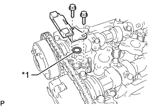
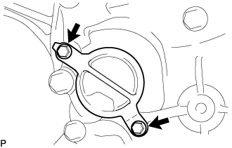
Обозначения на рисунке *1 Кольцевое уплотнение Выверните 2 болта и снимите направляющую цепного привода газораспределительного механизма с кольцевым уплотнением.
-
-
SET NO. 1 CYLINDER TO TDC/COMPRESSION
-
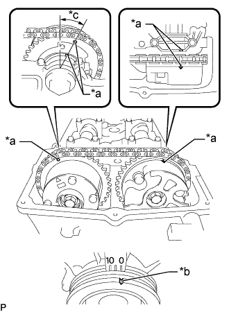
Text in Illustration *a Timing Mark *b Groove *c Approximately 13° Turn the crankshaft pulley, and align its groove with the "0" timing mark of the timing chain or belt cover sub-assembly.
-
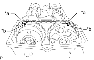
Check that the timing marks of the camshaft timing gear assembly and camshaft timing exhaust gear assembly are aligned with the timing marks of the No. 1 bearing cap as shown in the illustration.
Tech Tips
If the timing marks do not align, rotate the crankshaft clockwise again and align the timing marks.
-
-
REMOVE NO. 1 CHAIN TENSIONER ASSEMBLY
-
Text in Illustration *a Paint Mark *b Timing Mark Place paint marks on the chain sub-assembly, camshaft timing gear assembly and camshaft timing exhaust gear assembly.
-
Remove the 2 bolts and timing chain cover plate from the timing chain or belt cover sub-assembly.
-
Remove the gasket from the timing chain cover plate.
-
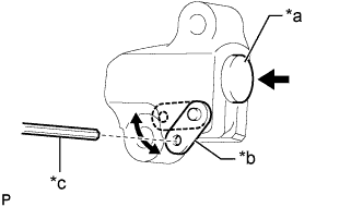
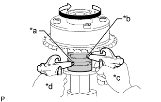
Text in Illustration *a Plunger *b Stopper Plate *c Hexagon Wrench Move the stopper plate upward to release the lock and push the plunger deep into the tensioner.
-
Move the stopper plate downward to set the lock and insert a hexagon wrench into the stopper plate hole.
-
Remove the bolt, nut, No. 1 chain tensioner assembly and gasket.
-
-
REMOVE NO. 2 CAMSHAFT
-
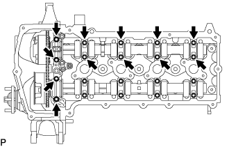
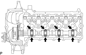
Uniformly loosen the 12 bolts and then remove the No. 1 camshaft bearing cap and 4 No. 2 camshaft bearing caps.
Note
Uniformly loosen the bolts while keeping the No. 2 camshaft level.
-
Move the camshaft in the direction shown in the illustration to loosen the chain sub-assembly, and then remove the No. 2 camshaft.
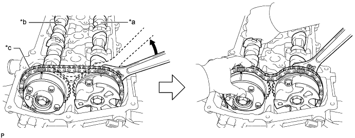
Text in Illustration *a Camshaft *b No. 2 Camshaft *c Chain Sub-assembly - - Note
Do not pry the No. 2 camshaft with a tool as an excessive amount of force may be applied to it.
-
-
REMOVE CAMSHAFT
-
Uniformly loosen the 8 bolts and then remove the 4 No. 2 camshaft bearing caps.
Note
Uniformly loosen the bolts while keeping the camshaft level.
-
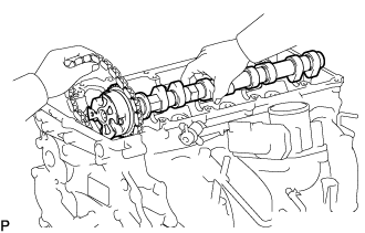
Remove the camshaft while holding the chain sub-assembly.
Note
Do not pry the camshaft with a tool as an excessive amount of force may be applied to it.
-
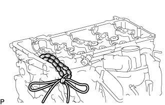
Secure the chain sub-assembly with a string as shown in the illustration.
Note
Be careful not to drop anything inside the timing chain or belt cover sub-assembly.
-
-
INSPECT CAMSHAFT TIMING GEAR ASSEMBLY
-
Check the lock of the camshaft timing gear assembly.
-
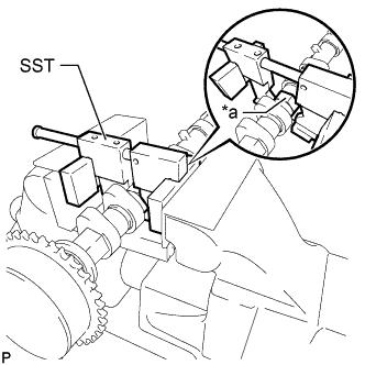
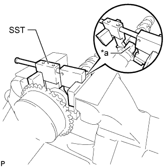
Text in Illustration *a Hexagonal Portion Using SST, grip the hexagonal portion, and then secure the SST and camshaft in a vise as shown in the illustration and check that the camshaft timing gear assembly does not rotate.
- SST
- 09212-31010
Note
-
Do not damage the camshaft.
-
Never grip areas other than the hexagonal portion, as this may cause damage.
-
-
Release the lock pin.
-
Clean the camshaft journal with non-residue solvent.
-
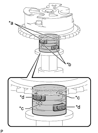
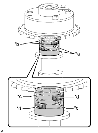
Text in Illustration *a Retard Side Path *b Advance Side Path *c Open *d Close 
Rubber Piece 
Vinyl Tape Cover the 4 oil paths of the cam journal with vinyl tape as shown in the illustration.
Tech Tips
1 retard side path and 1 advance side path are provided in the groove of the camshaft. Plug one of the paths with a rubber piece.
-
Break through the tape over the advance side path, and then break through the tape over the retard side path on the opposite side from the hole over the advance side path as shown in the illustration.
-
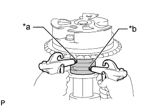
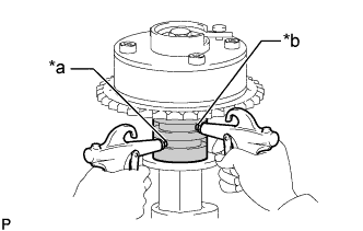
Text in Illustration *a Retard Side Path *b Advance Side Path Apply compressed air at approximately 200 kPa (2.0 kgf/cm2, 28 psi) to the 2 open paths accessible through the holes in the tape.
Note
Cover the paths with a piece of cloth when applying pressure to keep oil from splashing.
-
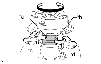
Text in Illustration *a Retard Side Path *b Advance Side Path *c Decompress *d Hold Pressure Check that the camshaft timing gear assembly revolves in the advance direction when reducing the air pressure applied to the retard side path.
OK Gear rotates in the advance direction. Tech Tips
This operation releases the lock pin which holds the timing gear in the most retarded position.
-
When the camshaft timing gear assembly reaches the most advanced position, release the air pressure from the retard side path and advance side path in that order.
Note
-
Do not release the air pressure from the advance side path first. The gear may abruptly shift in the retard direction and break the lock pin.
-
When releasing the air pressure from the advance side path, release it slowly.
-
-
-
Check for smooth rotation.
-
Rotate the camshaft timing gear assembly within its movable range several times, but do not turn it to the most retarded position. Check that the gear rotates smoothly.
CAUTION:
Do not use air pressure to perform the smooth operation check.
-
-
Check the lock in the most retarded position.
-
Confirm that the camshaft timing gear assembly becomes locked at the most retarded position.
-
-
-
REMOVE CAMSHAFT TIMING GEAR ASSEMBLY
-
Text in Illustration *a Hexagonal Portion Using SST, grip the hexagonal portion, and then secure the SST and camshaft in a vise as shown in the illustration.
- SST
- 09212-31010
Note
-
Do not damage the camshaft.
-
Never grip areas other than the hexagonal portion, as this may cause damage.
-
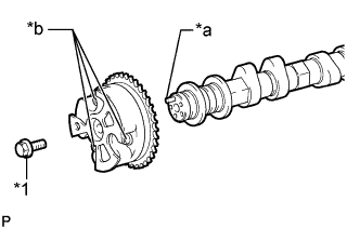
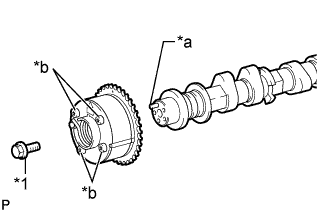
Text in Illustration *1 Flange Bolt *a Straight Pin *b Do Not Remove Remove the flange bolt and camshaft timing gear assembly.
Note
-
Be sure not to remove the other 3 bolts.
-
If planning to reuse the gear, be sure to release the straight pin lock before installing the gear.
-
-
-
INSPECT CAMSHAFT TIMING EXHAUST GEAR ASSEMBLY
-
Check the lock of the camshaft timing exhaust gear assembly.
-
Text in Illustration *a Hexagonal Portion Using SST, grip the hexagonal portion, and then secure the SST and No. 2 camshaft in a vise as shown in the illustration and check that the camshaft timing exhaust gear assembly does not rotate.
- SST
- 09212-31010
Note
-
Do not damage the No. 2 camshaft.
-
Never grip areas other than the hexagonal portion, as this may cause damage.
-
-
Text in Illustration *a Retard Side Path *b Advance Side Path *c Open *d Close Rubber Piece Vinyl Tape Release the lock pin.
-
Clean the No. 2 camshaft journal with non-residue solvent.
-
Cover the 4 oil paths of the cam journal with vinyl tape as shown in the illustration.
Tech Tips
There are 4 oil paths in the grooves of the No. 2 camshaft. Plug 2 paths with pieces of rubber.
-
Break through the tape over the advance side path, and then break through the tape over the retard side path on the opposite side from the hole over the advance side path as shown in the illustration.
-
Text in Illustration *a Retard Side Path *b Advance Side Path Apply compressed air at approximately 200 kPa (2.0 kgf/cm2, 28 psi) to the 2 open paths (the advance side path and retard side path).
Note
Cover the paths with a piece of cloth when applying pressure to keep oil from splashing.
Tech Tips
The lock pin is released in this condition.
-
Text in Illustration *a Retard Side Path *b Advance Side Path *c Decompress *d Hold Pressure Check that the camshaft timing exhaust gear assembly turns in the retard direction when reducing the air pressure applied to the advance side path.
Tech Tips
The lock pin is released and the camshaft timing exhaust gear assembly turns in the retard direction.
-
When the camshaft timing exhaust gear assembly moves to the most retarded position, release the air pressure from the advance side path, and then release the air pressure from the retard side path.
Note
Be sure to release the air pressure from the advance side path first. If the air pressure of the retard side path is released first, the camshaft timing exhaust gear assembly may abruptly shift in the advance direction and break the lock pin or other parts.
-
-
Check for smooth rotation.
-
Turn the camshaft timing exhaust gear assembly within its movable range (21.5 to 23.5°) 2 or 3 times, but do not turn it to the most advanced position. Make sure that the gear turns smoothly.
Note
When the air pressure is released from the advance side path and then from the retard side path, the gear automatically returns to the most advanced position due to the advance assist spring operation, and locks. Gradually release the air pressure from the retard side path before performing the smooth rotation check.
-
-
Check the lock at the most advanced position.
-
Make sure that the camshaft timing exhaust gear assembly locks at the most advanced position.
-
-
-
REMOVE CAMSHAFT TIMING EXHAUST GEAR ASSEMBLY
-
Text in Illustration *a Hexagonal Portion Using SST, grip the hexagonal portion, and then secure the SST and No. 2 camshaft in a vise as shown in the illustration.
- SST
- 09212-31010
Note
-
Do not damage the No. 2 camshaft.
-
Never grip areas other than the hexagonal portion, as this may cause damage.
-
Text in Illustration *1 Flange Bolt *a Straight Pin *b Do Not Remove Remove the flange bolt and camshaft timing exhaust gear assembly.
Note
Be sure not to remove the other 4 bolts.
-