- Click here
INSPECT CYLINDER HEAD SET BOLT
-
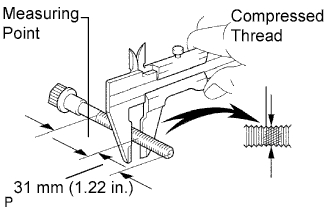
Using vernier calipers, measure the minimum outer diameter of the compressed thread at the measuring point.
Standard outer diameter 11.80 to 12.00 mm (0.4646 to 0.4724 in.) Minimum outer diameter 11.60 mm (0.4567 in.) If the outer diameter is less than the minimum, replace the bolt.
-
- Click here
INSTALL CYLINDER HEAD GASKET
-
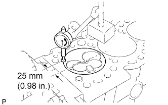
Check piston protrusion for each cylinder.
-
Clean the cylinder block with solvent.
-
Set the piston of the cylinder to be measured to slightly before TDC.
-
Place a dial indicator on the cylinder block, and set the measuring tip as shown in the illustration.
-
Set the dial indicator at 0 mm (0 in.).
Tip:
-
Use a dial indicator measuring tip as shown in the illustration.
-
Make sure that the measuring tip is square to the cylinder block gasket surface and piston head when taking the measurements.
-
-
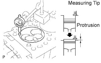
Find where the piston head protrudes most by slowly turning the crankshaft clockwise and counterclockwise.
-
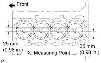
Measure the protrusion of each cylinder at 2 places as shown in the illustration, making a total of 8 measurements.
-
For the piston protrusion value of each cylinder, use the average of the 2 measurements of each cylinder.
Protrusion 0.68 to 0.97 mm (0.00268 to 0.0382 in.) Tip:If the protrusion is not as specified, remove the piston and connecting rod assembly and reinstall it.
-
-
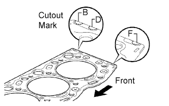
Select a new cylinder head gasket.
Tip:There are 3 sizes of new cylinder head gaskets, marked "B", "D" or "F" accordingly.
Table 1. New installed cylinder head gasket thickness: Mark B 1.40 to1.50 mm (0.0551 to 0.0591 in.) Mark D 1.50 to 1.60 mm (0.0591 to 0.0630 in.) Mark F 1.60 to 1.70 mm (0.0630 to 0.0669 in.)
-
Select the largest piston protrusion value from the measurements made, then select a new appropriate gasket according to the table below.
Piston protrusion mm (in.) Gasket size 0.68 to 0.77 (0.0268 to 0.0303) Use B 0.78 to 0.87 (0.0307 to 0.0343) Use D 0.88 to 0.97 (0.0346 to 0.0382) Use F
-
-
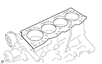
Place a new cylinder head gasket in position on the cylinder block.
Note:Be careful of the installation direction.
-
- Click here
INSTALL CYLINDER HEAD SUB-ASSEMBLY
Tip:Set the No.1 cylinder to 90° BTDC/compression to avoid interference with the piston top and valve head.
-
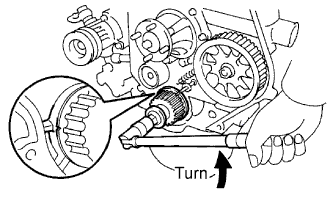
Using the crankshaft pulley bolt, turn the crankshaft 90° counterclockwise, and align the timing mark of the crankshaft timing pulley with the protrusion of the timing belt case.
-
Place the cylinder head in position on the cylinder head gasket.
-
Install cylinder head bolts.
Tip:
-
The cylinder head bolts are tightened in 3 progressive steps (steps (2), (4) and (5))
-
If any bolt is broken or deformed, replace it.
-
Apply a light coat of engine oil to the threads and under the heads of the cylinder head bolts.
-
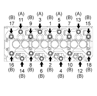
Install and uniformly tighten the 18 cylinder head bolts, in several steps, in the sequence shown.
78 N*m 800 kgf*cm 58 ft.*lbf Tip:Each bolt length is indicated below.
Bolt length:
107 mm (4.21 in.) for A
127 mm (5.00 in.) for B
If any one of the cylinder head bolts does not meet the torque specification, replace the cylinder head bolt.
-
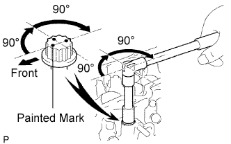
Mark the front of the cylinder head bolt with paint.
-
Retighten the cylinder head bolts 90° in the numerical order shown.
-
Retighten the cylinder head bolts by an additional 90°.
-
Check that the painted mark is now facing rearward.
-
-
- Click here
INSTALL CYLINDER HEAD COVER SUB-ASSEMBLY
-
Remove the any oil packing (FIPG) material.
-
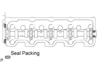
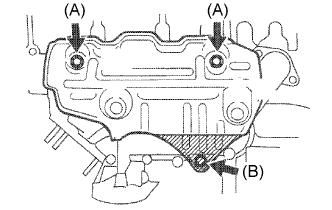
Apply seal packing to the cylinder head as shown in the illustration.
Seal packing Toyota Genuine Seal Packing Black, Three Bond 1207B or equivalent -
Install the gasket to the cylinder head cover.
-
Install the cylinder head cover with the 9 bolts and nut. Uniformly tighten the bolts and nuts in several steps.
12 N*m 120 kgf*cm 9 ft.*lbf -
Connect the ventilation hose.
-
- Click here
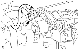
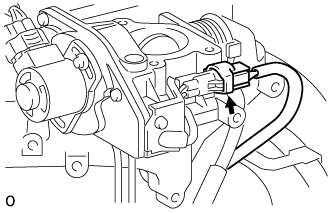
INSTALL GLOW PLUG NO.1 CONNECTOR
1.0 N*m 10 kgf*cm 9 in.*lbf - Click here
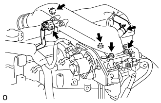
INSTALL INJECTION PIPE SET
-
Connect the 2 lower clamps on the intake manifold.
-
Install the 4 injection pipes.
25 N*m 250 kgf*cm 18 ft.*lbf -
Secure the injection pipes with the 2 upper pipe clamps and 2 nuts.
5.0 N*m 50 kgf*cm 44 in.*lbf
-
- Click here
INSTALL EXHAUST PIPE SUB-ASSEMBLY FRON NO.1 (for Long Wheelbase)
-
Install a new gasket and exhaust pipe sub-assembly front No.1 with the 3 bolts.
62 N*m 632 kgf*cm 46 ft.*lbf -
Tighten the clamp bolt, and install the exhaust pipe support bracket No.1 to the exhaust pipe sub-assembly front No.1.
-
- Click here
INSTALL EXHAUST PIPE SUB-ASSEMBLY FRON NO.1
-
Install a new gasket and exhaust pipe sub-assembly front No.1 with the 3 bolts.
62 N*m 632 kgf*cm 46 ft.*lbf -
Tighten the clamp bolt, install the exhaust pipe support bracket No.1 to the exhaust pipe sub-assembly front No.1.
-
- Click here
INSTALL EXHAUST PIPE SUB-ASSEMBLY FRONT NO.2 (for Long Wheelbase)
-
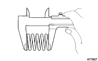
Inspect the compression spring.
-
Using vernier calipers, measure the free length of the compression springs.
Minimum length 40.5 mm (1.594 in.) Tip:If the free length is less than the minimum, replace the compression spring.
-
-
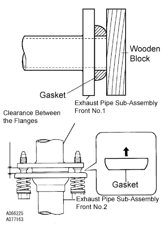
Install the gasket.
-
Fully insert a new gasket to the exhaust pipe sub-assembly front No.1 by hand.
-
Using a wooden block, uniformly strike the gasket so that the gasket and exhaust pipe sub-assembly front No.1 are properly fit.
Note:
-
Be careful with the installation direction of the gasket.
-
Do not damage the outer face.
-
Do not reuse the gasket.
-
To ensure a proper seal, do not use the exhaust pipe sub-assembly front No.2 to force the gasket onto the exhaust pipe sub-assembly front No.1.
-
-
-
Connect the exhaust pipe support, and install a new gasket and the exhaust pipe sub-assembly front No.2 with the 4 bolts, 2 nuts, and 2 compression springs.
Exhaust pipe sub-assembly front No.1 side 43 N*m 438 kgf*cm 32 ft.*lbf Exhaust pipe assembly tail side 48 N*m 489 kgf*cm 35 ft.*lbf Note:After installation, check that the clearance is almost same at any point between the flanges of the exhaust pipe sub-assembly front No.2 and exhaust pipe sub-assembly front No.1.
-
- Click here
INSTALL EXHAUST PIPE SUB-ASSEMBLY FRONT NO.2 (for Super Long Wheelbase)
-
Inspect the compression spring.
-
Using vernier calipers, measure the free length of the compression springs.
Minimum length 40.5 mm (1.594 in.) Tip:If the free length is less than the minimum, replace the compression spring.
-
-
Install the gasket.
-
Fully insert a new gasket to the exhaust pipe sub-assembly front No.1 by hand.
-
Using a wooden block, uniformly strike the gasket so that the gasket and exhaust pipe sub-assembly front No.1 are properly fit.
Note:
-
Be careful with the installation direction of the gasket.
-
Do not damage the gasket.
-
Do not reuse the gasket.
-
To ensure a proper seal, do not use the exhaust pipe sub-assembly front No.2 to force the gasket onto the exhaust pipe sub-assembly front No.1.
-
-
-
Connect the exhaust pipe support, and install a new gasket and the exhaust pipe sub-assembly front No.2 with the 4 bolts, 2 nuts, and 2 compression springs.
Exhaust pipe sub-assembly front No.1 side 43 N*m 438 kgf*cm 32 ft.*lbf Exhaust pipe assembly center side 48 N*m 489 kgf*cm 35 ft.*lbf Note:After installation, check that the clearance is almost same at any point between the flanges of the exhaust pipe sub-assembly front No.2 and exhaust pipe sub-assembly front No.1 .
-
- Click here
INSTALL EXHAUST MANIFOLD HEAT INSULATOR NO.1
-
Установите теплозащитный экран и закрепите его 3 болтами.
Болт (A) 18 Н*м 185 кгс*см 13 фунт-сила-футов Болт (B) 19 Н*м 195 кгс*см 14 фунт-сила-футов
-
- Click here
INSTALL VENTURI ASSEMBLY
-
Install a new gasket and venturi.
-
Connect the throttle control motor connector.
-
Connect the throttle open switch connector.
-
- Click here
INSTALL INTAKE AIR CONNECTOR SUB-ASSEMBLY
-
Install a new gasket and intake air connector with the bolt and 3 nuts.
bolt 18 N*m 184 kgf*cm 13 ft.*lbf Nut 12 N*m 122 kgf*cm 9 ft.*lbf -
Connect the turbo pressure sensor connector.
-
Connect the ventilation hose.
-
- Click here
CONNECT AIR CLEANER HOSE NO.2
-
Install the air cleaner hose No.2 with the clamp.
-
- Click here
INSTALL TIMING BELT
- Click here
CONNECT CABLE TO NEGATIVE BATTERY TERMINAL
- Click here
BLEED AIR FROM FUEL SYSTEM
-
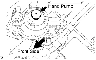
Using the hand pump, bleed air from the fuel system until pumping becomes difficult.
-
- Click here
ADD ENGINE COOLANT
-
Залейте охлаждающую жидкость в расширительный бачок радиатора до верха горловины.
Номинальный объем Параметр / Устройство Заданные условия Для моделей без подогревателя 12,3 литра (13,0 кварты США, 10,8 английской кварты) Для моделей с передним подогревателем 13,3 литра (14,1 кварты США, 11,7 английской кварты) Для моделей с передним и задним подогревателями 15,3 литра (16,2 кварты США, 13,5 английской кварты) Note:Не доливайте простую воду вместо охлаждающей жидкости двигателя.
Tip:
-
Использование неподходящей охлаждающей жидкости может привести к повреждению системы охлаждения двигателя.
-
Разрешается использовать только охлаждающую жидкость "TOYOTA Super Long Life Coolant" или аналогичную высококачественную охлаждающую жидкость на основе этиленгликоля (а не на силикатной, аминовой, нитритной или борнокислой основе), изготовленную по гибридной технологии органических кислот с длительным сроком годности (охлаждающая жидкость, изготовленная по гибридной технологии органических кислот, состоит из низкофосфатных соединений и органических кислот).
-
-
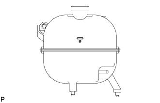
Долейте охлаждающую жидкость в расширительный бачок радиатора до отметки B и установите пробку расширительного бачка радиатора.
-
Прогревайте двигатель, пока не откроется термостат.
-
Когда термостат откроется, несколько минут прокачивайте охлаждающую жидкость.
Tip:Время открывания термостата можно проверить, сжав входной патрубок радиатора рукой и убедившись, что охлаждающая жидкость поступает в шланг.
-
-
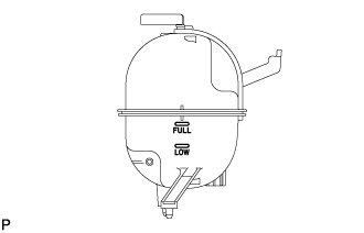
После охлаждения двигателя убедитесь, что уровень охлаждающей жидкости находится между отметками "LOW" и "FULL".
-
- Click here
CHECK FOR ENGINE COOLANT LEAKS
CAUTION:Не снимайте пробку радиатора, пока двигатель и радиатор не остынут. Выброс горячей охлаждающей жидкости и пара под давлением может стать причиной серьезных ожогов.
-
Заполните радиатор охлаждающей жидкостью и подсоедините к радиатору приспособление для опрессовки системы охлаждения и проверки пробки радиатора.
-
Прогрейте двигатель.
-
С помощью приспособления для опрессовки системы охлаждения и проверки пробки радиатора увеличьте давление в радиаторе до 118 кПа (1,2 кгс/см2, 17,1 фунтов на кв. дюйм) и убедитесь, что давление не падает.
Tip:Если давление снижается, проверьте на наличие утечек шланги, радиатор и насос системы охлаждения. При отсутствии внешних утечек проверьте сердцевину отопителя, блок цилиндров и головку блока цилиндров.
-
- Click here
CHECK FOR FUEL LEAKS
-
Check that there are no fuel leaks anywhere on the fuel system after doing maintenance.
Tip:When checking for fuel leaks, make sure that there is pressure in the fuel line.
-
- Click here
CHECK FOR EXHAUST GAS LEAKS
- Click here
CHECK IDLE SPEED
-
Warm up the engine.
-
When using an intelligent tester:
-
Connect the intelligent tester to the DLC3.
Idle speed 720 to 820 rpm (A/C OFF) 750 to 850 rpm (A/C ON) Tip:Refer to the intelligent tester operator's manual for further details.
-
-
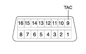
When not using an intelligent tester:
-
Using SST, connect the tachometer test probe to terminal 9 (TAC) of the DLC3.
09843-18040 -
Check the idle speed.
Idle speed 720 to 820 rpm (A/C OFF) 750 to 850 rpm (A/C ON) Note:Switch off all accessories.
-
-
- Click here
INSPECT MAXIMUM ENGINE SPEED
-
Start the engine.
-
Depress the accelerator pedal all the way.
-
Check the maximum speed.
Maximum speed 4,850 to 4,950 rpm
-
- Click here
PERFORM INITIALIZATION