БЛОК ДВИГАТЕЛЯ ПОВТОРНАЯ СБОРКА

-
INSTALL TIGHT PLUG
-
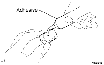
Apply adhesive to a new tight plug.
Adhesive Toyota Genuine Adhesive 1324, Three Bond 1324 or equivalent -
Using SST and a hammer, tap in the 2 tight plugs A.
- SST
- 09950-60010 ( 09951-00250 )
- 09950-70010 ( 09951-07100 )
-
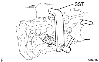
Using SST and a hammer, tap in the 4 tight plugs B.
- SST
- 09950-60010 ( 09951-00350 )
- 09950-70010 ( 09951-07100 )
-
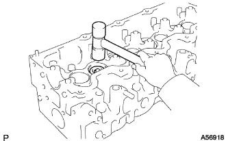
Using SST and a hammer, tap in the tight plug C.
- SST
- 09950-60010 ( 09951-00500 )
- 09950-70010 ( 09951-07100 )
-
-
INSTALL STUD BOLT
Note
If the stud bolt is deformed or the threads are damaged, replace it.
-
Install the stud bolts as shown in the illustration.
- Torque:
- 15 N*m { 150 kgf*cm, 11 ft.*lbf }
-
-
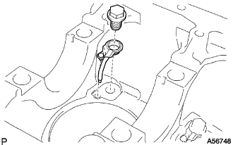
INSTALL STRAIGHT PIN
-
Install the straight pin as shown in the illustration.
-
-
INSTALL RING PIN
-
Install the ring pin as shown in the illustration.
-
-
INSTALL W/HEAD TAPER SCREW PLUG NO.1
-
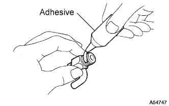
Apply adhesive to 2 or 3 threads.
Adhesive Toyota Genuine Adhesive 1324, Three Bond 1324 or equivalent -
Install the screw plug.
- Torque:
- 20 N*m { 200 kgf*cm, 14 ft.*lbf }
-
-
INSTALL CYLINDER BLOCK WATER DRAIN COCK SUB-ASSEMBLY
-
Apply adhesive to 2 or 3 threads.
Adhesive Toyota Genuine Adhesive 1324, Three Bond 1324 or equivalent -
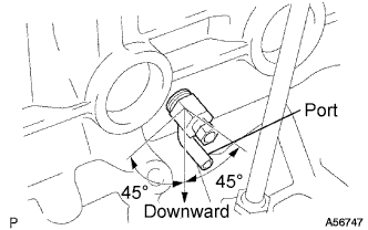
Install the water drain cock.
- Torque:
- 57 N*m { 580 kgf*cm, 42 ft.*lbf }
Tech Tips
-
After applying the specified torque, rotate the drain union clockwise until its drain port is facing downward.
-
The drain port may be set within 45°of either side of the prescribed position.
-
-
INSTALL CYLINDER BLOCK OIL ORIFICE
-
Using a 6 mm hexagon wrench, install the oil orifice.
- Torque:
- 11 N*m { 110 kgf*cm, 8 ft.*lbf }
-
-
INSTALL OIL NOZZLE NO.1 SUB-ASSEMBLY
-
Align the pin of the oil nozzle with the pin hole of the cylinder block.
-
Install the oil nozzle with the check valve. Install the 4 oil nozzles and check valves.
- Torque:
- 26 N*m { 260 kgf*cm, 18 ft.*lbf }
-
-
INSTALL CONNECTING ROD SMALL END BUSH
-
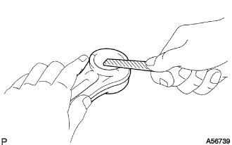
Using a round file, lightly file off any roughness from the small end of the connecting rod.
-
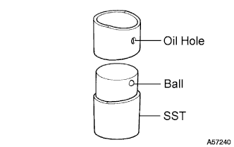
Attach a new bush to SST with the ball of SST inside the oil hole of the bush.
- SST
- 09222-54011 ( 09222-03021 )
-
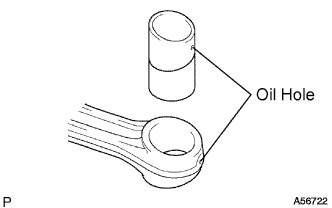
Align the oil holes of the bush and connecting rod.
-
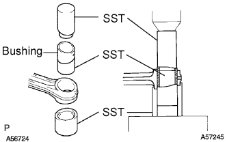
Using SST and a press, press in the bush.
- SST
- 09222-54011 ( 09222-03016, 09222-03021, 09222-03026 )
-
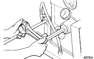
Using a pin hole grinder, hone the bush to obtain the standard specified clearance (See disassembly, step 69) between the bush and piston pin.
-
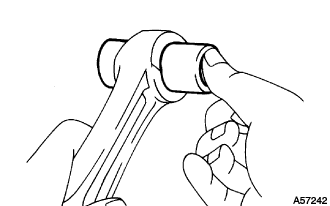
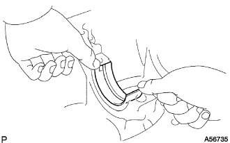
Check the piston pin fitting condition at normal room temperature. Coat the piston pin with engine oil, and push it into the connecting rod with your thumb.
-
-
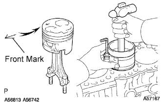
INSTALL PISTON SUB-ASSEMBLY W/PIN
-
Assemble the piston and connecting rod.
-
Using snap ring pliers, install a new snap ring on one side of the piston pin hole.
-
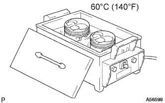
Gradually heat the piston to about 60°C (140°F).
-
Coat the piston pin with engine oil.
-
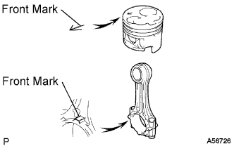
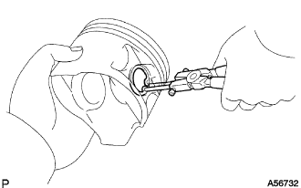
Align the front marks of the piston and connecting rod, and push in the piston pin with your thumb.
-
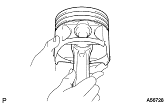
Check the fitting condition between the piston and piston pin.
Tech Tips
Try to move the piston back and forth on the piston pin.
-

Using snap ring pliers, install a new snap ring on the other side of the piston pin hole.
-
-
Install the piston rings.
-
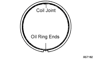
Install the coil and oil ring by hand.
Tech Tips
Face the end gap of the oil ring in the opposite direction of the coil joint.
-
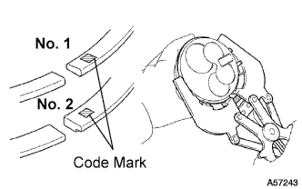
Using a piston ring expander, install the No. 1 and No. 2 piston rings with the code mark facing upward.
Code mark No. 1 1N No. 2 2N -
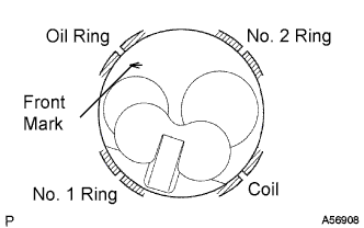
Position the piston rings so that the ring ends are as shown in the illustration.
Note
Do not align the ring ends.
-
-
-
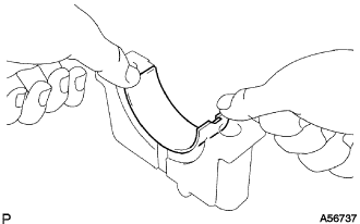
INSTALL CONNECTING ROD BEARING
-
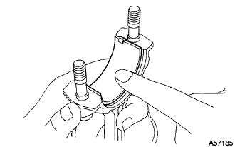
Align the bearing claw with the groove of the connecting rod or connecting rod cap.
-
Install the bearings in the connecting rod and connecting rod cap.
-
-
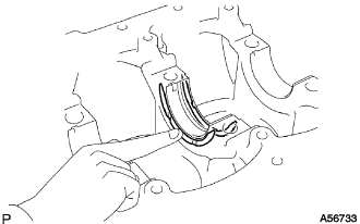
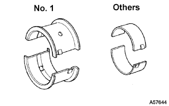
INSTALL CRANKSHAFT BEARING
Tech Tips
Upper bearings have an oil groove and oil hole; lower bearings do not.
-
Align the bearing claw with the claw groove of the cylinder block, and push in the 5 upper bearings.
-
Align the bearing claw with the claw groove of the crankshaft bearing cap, and push in the 5 lower bearings.
-
-
INSTALL CRANKSHAFT THRUST WASHER SET
-
Install the 2 thrust washers under the No. 3 journal position of the cylinder block with the oil grooves facing outward.
-
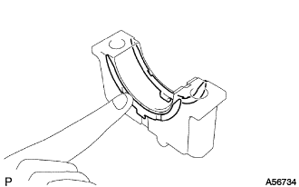
Install the 2 thrust washers on the No. 3 crankshaft bearing cap with the grooves facing outward.
-
-
INSTALL CRANKSHAFT
-
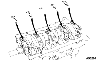
Place the crankshaft on the cylinder block.
-
Install the 5 crankshaft bearing caps in their proper locations.
-
Install the crankshaft bearing cap bolts.
-
Apply a light coat of the engine oil to the threads and under the bolt heads of the crankshaft bearing caps.
-
Install and uniformly tighten the 10 bolts of the crankshaft bearing caps, in several steps, in the sequence shown.
- Torque:
- 105 N*m { 1,071 kgf*cm, 77 ft.*lbf }
-
-
Check that the crankshaft turns smoothly.
-
Check the crankshaft thrust clearance (See disassembly, step 53).
-
-
INSTALL PISTON AND CONNECTING ROD
-
Cover the connecting rod bolts with a short piece of hose to protect the crankshaft and cylinder bore from damage.
-
Using a piston ring compressor, push the correctly numbered piston and connecting rod assembly into the cylinder with the front mark of the piston facing forward.
-
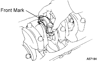
Place the connecting rod cap on the connecting rod.
-
Match the numbered connecting rod cap with the connecting rod.
-
Install the connection rod cap with the front mark facing forward.
-
-
Install the connecting rod cap nuts.
Tech Tips
The connecting rod cap nuts are tightened in 2 progressive steps (steps (2) and (4)).
If any connecting rod bolt is broken or deformed, replace it.
-
Apply a light of engine oil to the threads and under the heads of the connecting rod cap nuts.
-
Install and alternately tighten the nuts of the connecting rod cap in several passes.
- Torque:
- 54 N*m { 550 kgf*cm, 40 ft.*lbf }
If any one of the connecting rod cap nuts does not meet the torque specification, replace them.
-
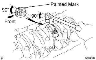
Mark the front of the connecting rod cap nuts with paint.
-
Retighten the connecting rod cap nuts 90° as shown.
-
Check that the painted mark is now at a 90° angle to the front.
-
-
Check that the crankshaft turns smoothly.
-
Check the connecting rod thrust clearance (See disassembly, step 49).
-
-
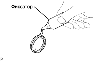
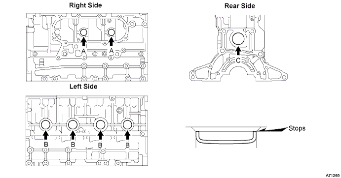
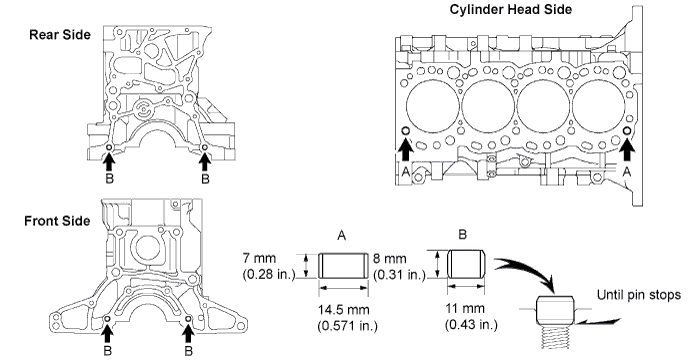
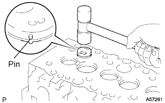
INSTALL TIGHT PLUG
Note
If water leaks from the tight plug or the plug corrodes, replace it.
-
Apply adhesive to the tight plug.
Adhesive Toyota Genuine Adhesive 1324, Three Bond 1324 or equivalent -
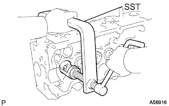
Using SST, tap in new 7 tight plugs A.
- SST
- 09950-60010 ( 09951-00250 )
- 09950-70010 ( 09951-07100 )
-
Using SST, tap in new tight plug B.
- SST
- 09950-60010 ( 09951-00300 )
- 09950-70010 ( 09951-07100 )
-
Using SST, tap in new 2 tight plugs C.
- SST
- 09950-60010 ( 09951-00450 )
- 09950-70010 ( 09951-07100 )
-
-
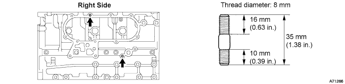
INSTALL STUD BOLT
Note
If the stud bolt is deformed or the threads are damaged, replace it.
-
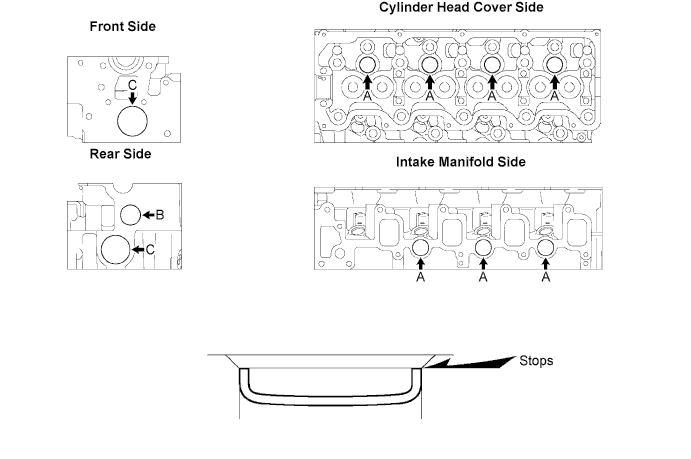
Install the stud bolts as shown in the illustration.
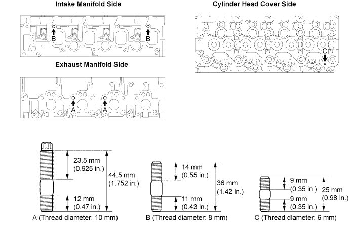
- Torque:
- Bolt A
- 26 N*m { 265 kgf*cm, 19 ft.*lbf }
- Bolt B
- 12 N*m { 120 kgf*cm, 9 ft.*lbf }
- Bolt C
- 6.0 N*m { 60 kgf*cm, 53 in.*lbf }
-
-
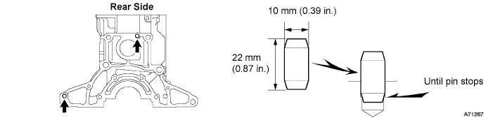
INSTALL RING PIN
Note
It is not necessary to remove the ring pin unless it is being replaced.
-
Using a plastic hammer, tap in a new ring pin until it stops.
-
-
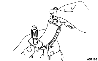
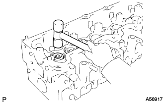
INSTALL SEMICIRCULAR PLUG
-
Remove any old packing (FIPG) material.
-
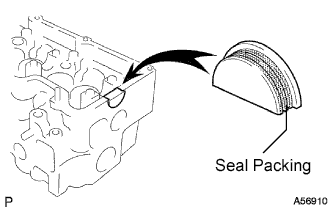
Apply seal packing to the semicircular plug as shown in the illustration.
Seal packing Toyota Genuine Seal Packing Black, Three Bond 1207B or equivalent -
Install the semicircular plug to the cylinder head.
-
-
INSTALL COMBUSTION CHAMBER SUB-ASSEMBLY
-
Select the number of shim, depending on the table below.
Select the number of shim Number mark of cylinder head Number of shim 1 0 2 0 1 3 1 2 Shim thickness 0.03 mm (0.0012 in.) -
Align the combustion chamber knock pin with the cylinder head notch.
-
Using a plastic hammer, tap in the combustion chamber.
-
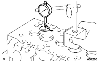
Using a dial indicator, check the combustion chamber protrusion.
Combustion chamber protrusion Minus 0.03 to Plus 0.03 mm (Minus 0.0012 to Plus 0.0012 in.) If the protrusion is less than the specified, adjust with shims.
If the protrusion is greater than the specified, replace the chamber and recheck the protrusion.
-
-
INSTALL VALVE STEM OIL SEAL
-
INSTALL INTAKE VALVE
-
Install the valve, spring seat, valve spring and spring retainer.
-
Using SST, compress the valve spring and place the 2 retainer locks around the valve stem.
- SST
- 09202-70020 ( 09202-00030 )
-
Using a plastic hammer, lightly tap the valve stem tip to assure a proper fit.
Note
Do not damage the valve stem tip.
-
-
INSTALL EXHAUST VALVE
-
Install the valve, spring seat, valve spring and spring retainer.
-
Using SST, compress the valve spring and place the 2 retainer locks around the valve stem.
- SST
- 09202-70020 ( 09202-00030 )
-
Using a plastic hammer, lightly tap the valve stem tip to assure a proper fit.
Note
Do not damage the valve stem tip.
-
-
INSTALL VALVE LIFTER
-
Install the valve lifter and shim.
-
Check that the valve lifter rotates smoothly by hand.
-
-
INSTALL ENGINE REAR OIL SEAL
-
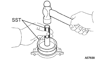
Using SST and a hammer, tap in a new oil seal until its surface is flush with the oil seal retainer edge.
- SST
- 09223-15030
- 09950-70010 ( 09951-07100 )
-
Apply MP grease to the oil seal lip.
-
-
INSTALL ENGINE REAR OIL SEAL RETAINER
-
Install a new gasket and the retainer with the 4 bolts.
- Torque:
- 13 N*m { 130 kgf*cm, 10 ft.*lbf }
-
-
INSTALL TIMING GEAR CASE OR TIMING CHAIN CASE OIL SEAL
-
Using SST and a hammer, tap in a new oil seal to the depth of 0.5 mm (0.020 in.) from the oil pump case edge.
- SST
- 09214-60010
-
Apply MP grease to the oil seal lip.
-
-
INSTALL TIMING GEAR CASE SUB-ASSEMBLY
-
Place a new gasket on the cylinder block.
-
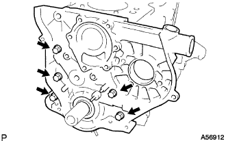
Install the timing gear case with the 5 bolts.
- Torque:
- 23 N*m { 230 kgf*cm, 17 ft.*lbf }
-
-
INSTALL OIL STRAINER SUB-ASSEMBLY
-
Install a new gasket and oil strainer with the 2 bolts and 2 nuts.
- Torque:
- Nut
- 21 N*m { 210 kgf*cm, 15 ft.*lbf }
- Bolt
- 18 N*m { 180 kgf*cm, 13 ft.*lbf }
-
-
INSTALL OIL PAN SUB-ASSEMBLY
-
Remove any old packing (FIPG) material. Do not drop any oil on the contact surfaces of the oil pan and cylinder block.
Note
Do not use a solvent which will affect the painted surfaces.
Tech Tips
-
Using a razor blade and gasket scraper, remove all the old packing (FIPG) material from the gasket surfaces and sealing groove.
-
Thoroughly clean all components to remove all the loose material.
-
Using a non-residue solvent, clean both sealing surfaces.
-
-
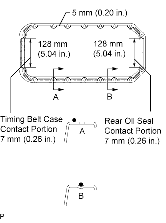
Apply seal packing to the oil pan as shown in the illustration.
Seal packing Toyota Genuine Seal Packing Black, Three Bond 1207B or equivalent Tech Tips
-
Apply at least 5.0 mm (0.20 in.) (preferably slightly more) of seal packing to the portions of the oil pan in contact with the timing belt case and rear oil seal retainer.
-
Install a nozzle with a 4.0 to 5.0 mm (0.16 to 0.20 in.) opening.
-
Do not apply an excessive amount to the surface especially near the oil passages.
-
Parts must be assembled within 5 minutes of application. Otherwise the material must be removed and reapplied.
-
Immediately remove the nozzle from the tube and reinstall cap.
-
-
Install the oil pan with the 16 bolts and 2 nuts. Uniformly tighten the bolts and nuts in several steps.
- Torque:
- 18 N*m { 180 kgf*cm, 13 ft.*lbf }
-
-
INSTALL CRANKSHAFT TIMING PULLEY
-
Align the pulley set key with the key groove of the timing pulley.
-
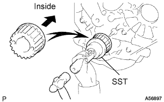
Using SST and a hammer, tap in the timing pulley, facing the flange side inward.
- SST
- 09223-46011
-
-
INSTALL WATER PUMP ASSEMBLY
-
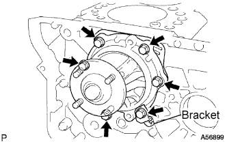
Install a new gasket, the water pump and tension spring bracket with the 6 bolts.
- Torque:
- 23 N*m { 230 kgf*cm, 17 ft.*lbf }
-
-
INSTALL TIMING BELT IDLER SUB-ASSEMBLY NO.2
-
Install the spacer and timing belt idler No.2 with the bolt.
- Torque:
- 33 N*m { 340 kgf*cm, 24 ft.*lbf }
-
Check that the timing belt idler No.2 moves smoothly.
-
-
INSTALL TIMING BELT IDLER SUB-ASSEMBLY NO.1
-
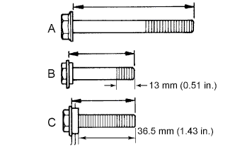
The bolt lengths for bolts A, B and C are shown in the illustration.
Tech Tips
Bolt C is combined with the timing belt idler No.1.
Bolt A 76.5 mm (3.012 in.) Bolt B 42.9 mm (1.689 in.) Bolt C 41.3 mm (1.626 in.) -
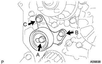
Install the timing belt idler No.1 with the 3 bolts.
-
Tighten the bolt C.
- Torque:
- 19 N*m { 195 kgf*cm, 14 ft.*lbf }
-
-
INSTALL CYLINDER HEAD GASKET
-
Check the piston protrusion for each cylinder.
-
Clean the cylinder block with solvent.
-
Set the piston of the cylinder to be measured to slightly before TDC.
-
Place a dial indicator on the cylinder block, and set the measuring tip as shown in the illustration.
-
Set the dial indicator at 0 mm (0 in.).
Tech Tips
-
Use a dial indicator measuring tip as shown in the illustration.
-
Make sure that the measuring tip is square to the cylinder block gasket surface and piston head when taking the measurements.
-
-
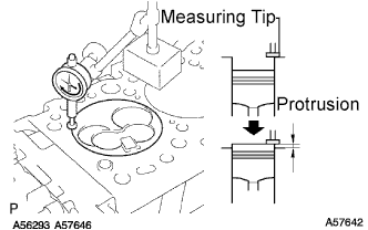
Find where the piston head protrudes most by slowly turning the crankshaft clockwise and counterclockwise.
-
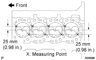
Measure the protrusion of each cylinder at 2 places as shown in the illustration, making a total of 8 measurements.
-
For the piston protrusion value of each cylinder, use the average of the 2 measurements of each cylinder.
Piston protrusion 0.68 to 0.97 mm (0.0268 to 0.0382 in.) If the protrusion is not as specified, remove the piston and connecting rod assembly and reinstall it.
-
-
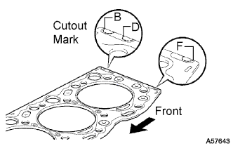
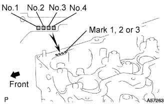
Select a new cylinder head gasket.
Tech Tips
There are 3 sizes of new cylinder head gaskets, marked B, D or F accordingly.
New installed cylinder head gasket thickness Cut out mark Thickness B 1.40 to 1.50 mm (0.0551 to 0.0591 in.) D 1.50 to 1.60 mm (0.0591 to 0.0630 in.) F 1.60 to 1.70 mm (0.0630 to 0.0669 in.)
-
Select the largest piston protrusion value from the measurements made, then select a new appropriate gasket according to the table below.
Piston protrusion Gasket size 0.68 to 0.77 mm (0.0268 to 0.0303 in.) Use B 0.78 to 0.87 mm (0.0307 to 0.0343 in.) Use D 0.88 to 0.97 mm (0.0346 to 0.0382 in.) Use F
-
-
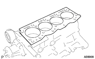
Place a new cylinder head gasket in position on the cylinder block.
Note
Be careful of the installation direction.
-
-
INSTALL CYLINDER HEAD SUB-ASSEMBLY
-
Place the cylinder head in position on the cylinder head gasket.
-
Install the cylinder head bolts.
Tech Tips
The cylinder head bolts are tightened in 3 progressive steps (steps (2), (4) and (5)).
If any bolt is broken or deformed, replace it.
-
Apply a light coat of engine oil to the threads and under the heads of the cylinder head bolts.
-
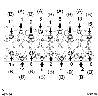
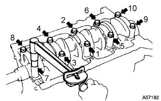
Install and uniformly tighten the 18 cylinder head bolts, in several steps, in the sequence shown.
- Torque:
- 78 N*m { 800 kgf*cm, 58 ft.*lbf }
If any one of the cylinder head bolts does not meet the torque specification, replace them.
Tech Tips
Each bolt length is indicated below.
Bolt A 107 mm (4.12 in.) Bolt B 127 mm (5.00 in.) -
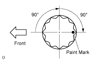
Mark the front of the cylinder head bolt with paint.
-
Retighten the cylinder head bolts 90° in the numerical order shown.
-
Retighten the cylinder head bolts by an additional 90° .
-
Check that the painted mark is now facing rearward.
-
-
-
INSTALL CAMSHAFT
-
Set the No.1 cylinder to 90° BTDC/compression.
Tech Tips
Set the No.1 cylinder to 90° BTDC/compression to avoid interference with the piston top and valve head.
-
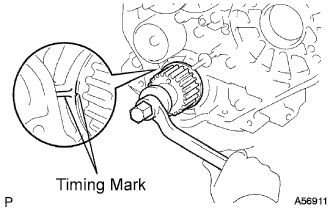
Using the crankshaft pulley bolt, turn the crankshaft, and put the timing mark of the crankshaft timing pulley with the protrusion of the timing belt case.
-
-
Install the camshaft.
Note
Different bearings are used for the No.1 and others.
-
Install the 10 bearings to the bearing caps and cylinder head.
-
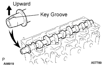
Place the camshaft on the cylinder head, with the key groove facing upward.
-
Install the 5 bearing caps in their proper locations.
-
Apply a light coat of engine oil to the threads and under the heads of the bearing cap bolts.
-
Install and uniformly tighten the 10 bearing cap bolts, in several steps, in the sequence shown.
- Torque:
- 25 N*m { 255 kgf*cm, 18 ft.*lbf }
-
-
-
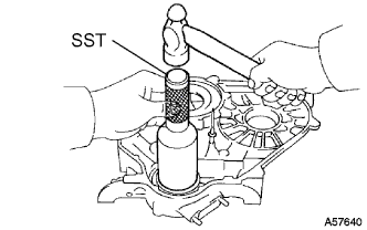
INSTALL OIL SEAL RETAINER NO.2 OIL SEAL
-
Using SST and a hammer, tap in a new oil seal until its surface is flush with the oil seal retainer edge.
- SST
- 09223-46011
-
Apply MP grease to the oil seal lip.
-
-
INSTALL CAMSHAFT OIL SEAL RETAINER
-
Install a new gasket and the retainer with the 4 bolts.
- Torque:
- 18 N*m { 185 kgf*cm, 13 ft.*lbf }
-
-
INSTALL TIMING BELT COVER NO.2
-
Install the timing belt cover with the 4 bolts.
- Torque:
- 18 N*m { 185 kgf*cm, 13 ft.*lbf }
-
-
INSTALL CAMSHAFT TIMING PULLEY
-
Install the woodruff key to the key groove of the camshaft.
-
Align the pulley set key with the timing mark facing outward.
-
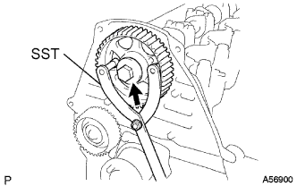
Using SST, install the pulley with the bolt.
- SST
- 09960-10010 ( 09962-01000, 09963-01000 )
- Torque:
- 98 N*m { 1,000 kgf*cm, 72 ft.*lbf }
-
-
INSPECT VALVE CLEARANCE
-
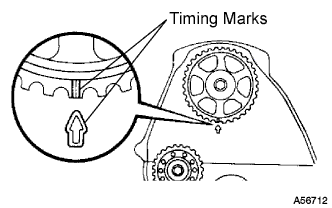
Align the timing mark of the camshaft timing pulley with the arrow mark of the timing belt No. 2 cover.
-
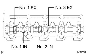
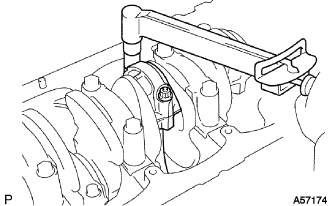
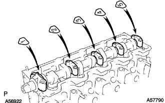
Check only the valves indicated in the illustration.
-
Using a feeler gauge, measure the clearance between the valve lifter and camshaft.
-
Record the out-of-specification valve clearance measurements. They will be used later to determine the required replacement adjusting shim.
Valve clearance (Cold) Valve Clearance Intake 0.20 to 0.30 mm (0.008 to 0.012 in.) Exhaust 0.40 to 0.50 mm (0.016 to 0.020 in.) -

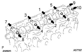
Turn the camshaft 1/2 revolutions (180°).
-
Check only the valves indicated in the illustration. Measure the valve clearance (See procedure (b) above).
-
-
-
ADJUST VALVE CLEARANCE
-
Remove the adjusting shim.
-
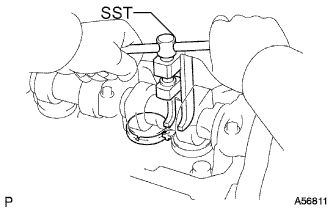
Turn the crankshaft so that the cam lobe of the camshaft on the adjusting valve points upward.
-
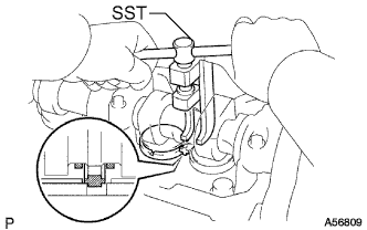
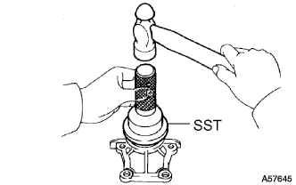
Using SST, press down the valve lifter.
- SST
- 09248-64011
-
Position the notch of the valve lifter with it facing the exhaust manifold side.
-
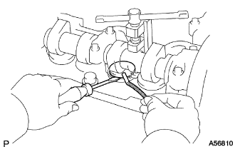
Remove the adjusting shim with a screwdriver and magnetic finger.
-
-
Determine the replacement adjusting shim size by following the formula or charts:
-
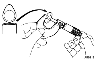
Using a micrometer, measure the thickness of the removed shim.
-
Calculate the thickness of a new shim so that the valve clearance comes within the specified value.
Tech Tips
-
T = Thickness of removed shim
-
A = Measured valve clearance
-
N = Thickness of new shim
Intake N = T + (A - 0.25 mm (0.010 in.)) Exhaust N = T + (A - 0.45 mm (0.018 in.))
-
-
Select a new shim with a thickness as close as possible to the calculated value.
Tech Tips
Shims are available in 17 sizes in increments of 0.05 mm (0.0020 in.), from 2.50 mm (0.0984 in.) to 3.30 mm (0.1299 in.).
-
Select the adjusting shim using the following chart (Intake).
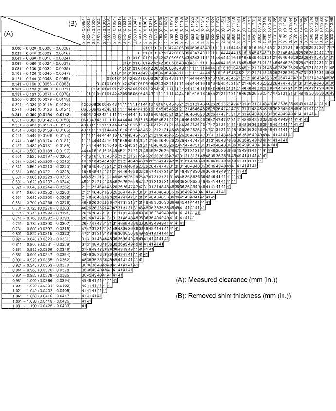
Intake valve clearance (Cold) 0.20 to 0.30 mm (0.008 to 0.012 in.) Tech Tips
The 2.800 mm (0.1102 in.) shim is installed and the measured clearance is 0.350 mm (0.0138 in.). Replace the 2.800 mm (0.1102 in.) shim with a No.21 shim.
Shim No. Thickness Shim No. Thickness 01 2.50 mm (0.0984 in.) 46 2.95 mm (0.1161 in.) 42 2.55 mm (0.1004 in.) 26 3.00 mm (0.1181 in.) 0.6 2.60 mm (0.1024 in.) 47 3.05 mm (0.1201 in.) 43 2.65 mm (0.1043 in.) 31 3.10 mm (0.1220 in.) 11 2.70 mm (0.1063 in.) 48 3.15 mm (0.1240 in.) 44 2.75 mm (0.1083 in.) 36 3.20 mm (0.1260 in.) 16 2.80 mm (0.1102 in.) 49 3.25 mm (0.1280 in.) 45 2.85 mm (0.1122 in.) 41 3.30 mm (0.1299 in.) 21 2.90 mm (0.1142 in.) - - -
Select the adjusting shim using the following chart (Exhaust).
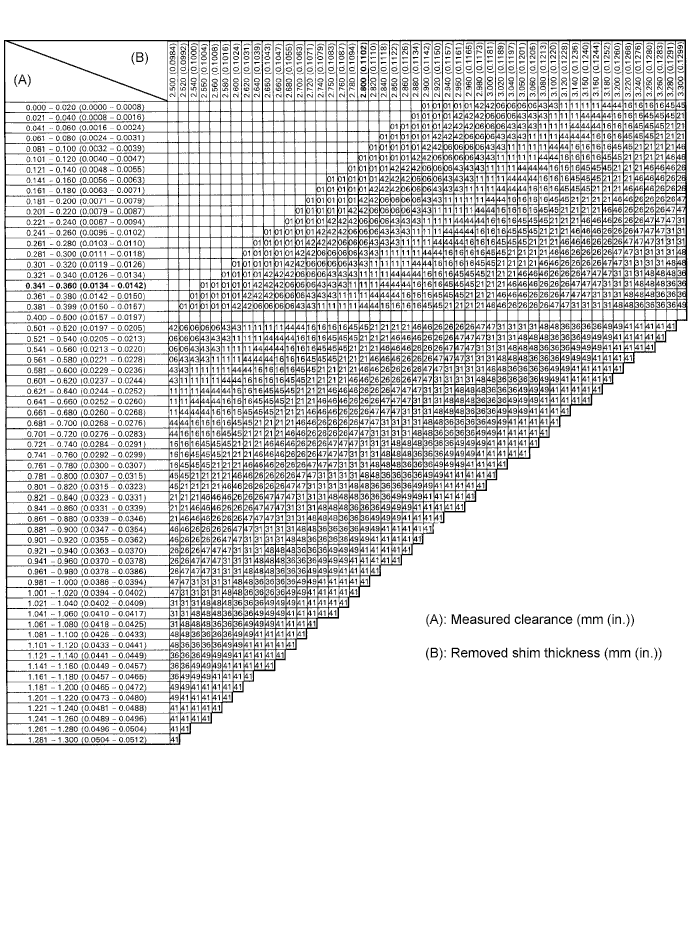
Exhaust valve clearance (Cold) 0.40 to 0.50 mm (0.016 to 0.020 in.) Tech Tips
The 2.800 mm (0.1102 in.) shim is installed and the measured clearance is 0.350 mm (0.0138 in.). Replace the 2.800 mm (0.1102 in.) shim with a No. 11 shim.
Shim No. Thickness Shim No. Thickness 01 2.50 mm (0.0984 in.) 46 2.95 mm (0.1161 in.) 42 2.55 mm (0.1004 in.) 26 3.00 mm (0.1181 in.) 06 2.60 mm (0.1024 in.) 47 3.05 mm (0.1201 in.) 43 2.65 mm (0.1043 in.) 31 3.10 mm (0.1220 in.) 11 2.70 mm (0.1063 in.) 48 3.15 mm (0.1240 in.) 44 2.75 mm (0.1083 in.) 36 3.20 mm (0.1260 in.) 16 2.80 mm (0.1102 in.) 49 3.25 mm (0.1280 in.) 45 2.85 mm (0.1122 in.) 41 3.30 mm (0.1299 in.) 21 2.90 mm (0.1142 in.) - -
-
-
Install a new adjusting shim.
-
Place a new adjusting shim on the valve lifter.
-
Remove the SST.
-
-
Recheck the valve clearance.
-
-
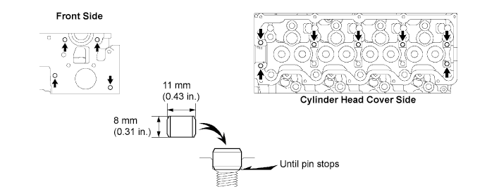
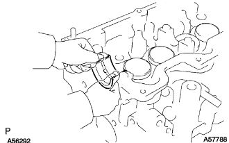
INSTALL CYLINDER HEAD COVER SUB-ASSEMBLY
-
Remove any old packing (FIPG) material.
-
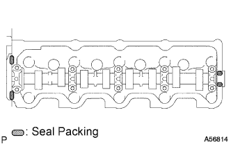
Apply seal packing to the cylinder head as shown in the illustration.
Seal packing Toyota Genuine Seal Packing Black, Three Bond 1207B or equivalent -
Install the gasket to the cylinder head cover.
-
Install the cylinder head cover with the 9 bolts and nut. Uniformly tighten the bolts and nuts in several steps.
- Torque:
- 12 N*m { 120 kgf*cm, 9 ft.*lbf }
-
-
INSTALL OIL FILLER CAP SUB-ASSEMBLY