ГОЛОВКА БЛОКА ЦИЛИНДРОВ УСТАНОВКА

-
INSTALL CYLINDER HEAD GASKET
-
Check each piston head protrusion.
-
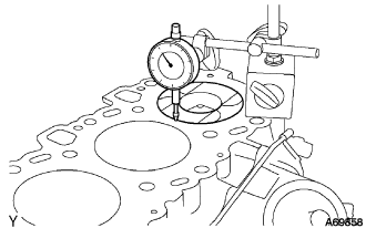
Using a dial indicator, measure the amount of each piston head protrusion between the top surfaces of each cylinder head and piston head.
Note
Set the dial indicator in an upright position to the cylinder block.
-
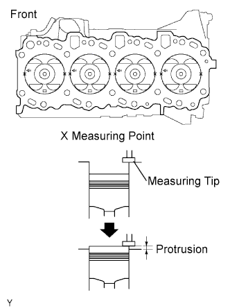
Perform the measurement at 2 places for each cylinder as shown in the illustration, making a total of 8 measurements.
-
For the piston protrusion value of each cylinder, use the average of the 2 measurements of each cylinder.
Protrusion 0.005 to 0.255 mm(0.00020 to 0.01004 in.) Tech Tips
Measurement should be done at 2 locations, right and left sides of each piston head.
-
-
Select an appropriate cylinder head gasket.
Tech Tips
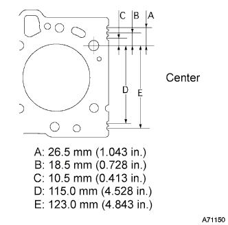
Each cylinder head gasket A to E has a unique notch position at its back-end, which helps identify an individual gasket.
-
Find the maximum value among all the measured piston head protrusion length to select an appropriate cylinder head gasket from A to E.
Piston protrusion Gasket size Piston protrusion mm (in.) A 0.005 to 0.054 (0.0002 to 0.00213) B 0.055 to 0.104 (0.00217 to 0.00409) C 0.105 to 0.154 (0.00413 to 0.00606) D 0.155 to 0.204 (0.00610 to 0.00803) E 0.205 to 0.255 (0.00807 to 0.01004) Cylinder head gasket thickness Gasket size Gasket thickness mm (in.) A 0.80 to 0.90 (0.0315 to 0.0354) B 0.85 to 0.95 (0.0335 to 0.0374) C 0.90 to 1.00 (0.0354 to 0.0394) D 0.95 to 1.05 (0.0374 to 0.0413) E 1.00 to 1.10 (0.0394 to 0.0433) -
Install the selected gasket to the cylinder block.
Note
Clean the top surface of the cylinder block and the underside of the cylinder head.
-
-
-
INSTALL CYLINDER HEAD SUB-ASSEMBLY
-
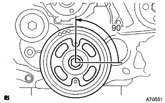
Set the crankshaft at 90° position in a counterclockwise direction from the TDC.
-
Set a new cylinder head gasket and install the cylinder head.
Tech Tips
Temporarily set a new gasket to the turbocharger before installing the cylinder head.
-
Apply a small amount of engine oil to each cylinder head bolt, screw, and washer.
-
Set the washers to the cylinder head bolts, and insert the bolts to the cylinder head.
-
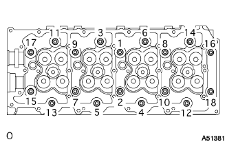
Tighten the cylinder head bolts equally in the specific order shown in the illustration in several steps, and then tighten them with the specified torque completely.
- Torque:
- 85 N*m { 867 kgf*cm, 63 ft.*lbf }
-
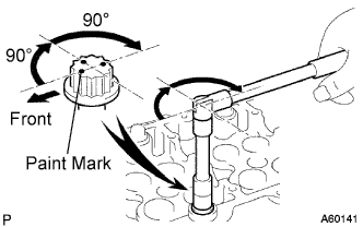
Put a paint mark on the top surface of the cylinder bolt head in the engine front direction.
-
Tighten each cylinder head bolt by 90°.
Tech Tips
The cylinder head bolts must be tightened in the specified order.
-
Tighten the bolts by additional 90°.
-
Make sure that all the paint marks come toward the opposite side to the engine front.
-
-
INSTALL CAMSHAFT
-
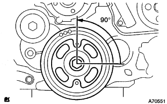
Set the crankshaft to 90° position from the TDC/compression.
-
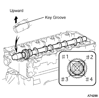
Place the camshaft to the cylinder head as shown in the illustration.
Note
Apply engine oil to the cams, thrusts and gears of the camshaft as well as on the journal of the cylinder head.
-
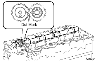
Align the dot marks of the camshaft and No.2 camshaft by meshing the both gears before placing the No.2 camshaft.
-
Remove old packing (FIPG) from the camshaft bearing cap.
-
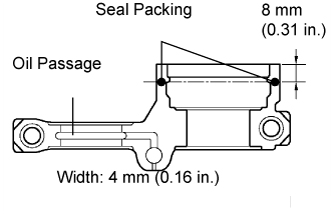
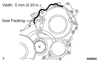
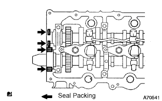
Apply seal packing to the specific places shown in the illustration.
Seal packing Toyota Genuine Seal Packing Black, Three Bond 1207B or equivalent Thickness 1 mm (0.04 in.) Note
-
Be careful not to adhere FIPG to the oil passage of the bearing cap.
-
After applying FIPG, install the camshaft bearing cap within 3 minutes and then tighten its bolts within 15 minutes.
-
Do not start the engine 2 hours after the installation.
-
-
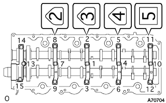
Install the camshaft bearing cap as shown in the illustration.
-
Tighten the 15 bolts for the camshaft bearing cap in the specified order shown in the illustration.
- Torque:
- 19 N*m { 194 kgf*cm, 14 ft.*lbf }
-
Adjust and inspect valve clearance.
-
Fix the timing belt cover No.2 with the 4 bolts and nuts.
- Torque:
- 10 N*m { 102 kgf*cm, 7 ft.*lbf }
-
Tighten the bolt for the camshaft timing pulley while holding the camshaft with a monkey wrench.
- Torque:
- 98 N*m { 1,000 kgf*cm, 72 ft.*lbf }
-
Adjust and inspect the valve clearance. Click here
-
Remove the camshaft timing pulley and timing belt cover No.2.
-
-
-
INSTALL CAMSHAFT SETTING OIL SEAL
-
Apply a bit of MP grease to a new oil seal's lip.
Note
Keep the lip clean. Do not to bring dirt and dust on that area.
-
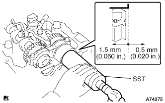
Using SST and a hammer, fit the oil seal.
- SST
- 09608-06041
Oil seal depth from flat end face 0.5 to 1.5 mm (0.020 to 0.060 in.) Note
Install the oil seal straight.
-
-
INSTALL INJECTOR ASSEMBLY
Note
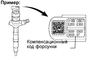
It is necessary to register the injector compensation code manually in the ECM using the intelligent tester, as each injector assembly has a different injection characteristic.
-
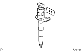
Put tags with cylinder numbers (#1 to #4) onto the new injector assembly in order to make sure of the right combinations with the right cylinders.
Standard Resistance 0.85 to 1.05 Ω at 20°C (69°F) -
Register the injector compensation code manually Click here.
-
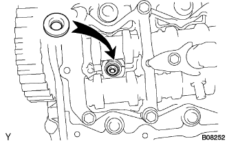
Install a new injection nozzle sheet to the cylinder head.
-
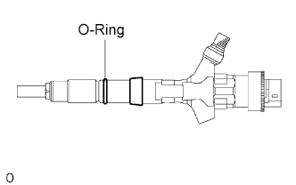
Install a new O-ring.
Tech Tips
Apply a light coat of engine oil to the O-ring.
-
Install the injector assembly to each cylinder referring to the tags with cylinder numbers (#1 to #4).
Note
If the wrong injector assembly is installed on the cylinder, rough idling or noise may occur.
-
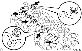
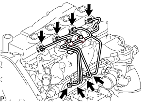
Temporarily install the 4 injection pipes.
Note
In case of having replaced the injector, replace the injection pipe, too.
Tech Tips
Tighten the union nuts of the injection pipes by hand until them cannot turn.
-
Apply a light coat of engine oil to the 4 hollow screws and union bolt.
-
Temporarily install the nozzle leakage pipe assembly and 5 new nozzle leakage pipe gaskets and tighten the 4 hollow screws, union bolt by hand until them cannot turn.
Note
Confirm the deformation and damage the injector hollow screws, and union bolt.
-
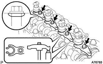
Install the 4 nozzle holder clamps and 4 new washers with the 4 bolts as show in the illustration.
-
Tighten the new washers and 4 bolts.
- Torque:
- 22 N*m { 220 kgf*cm, 16 ft.*lbf }
Note
-
Pay attention the direction of washers.
-
Clip the injector at the fork portion with a clamp which is set on the head of the cam cap bolt. At this time, check that the clamp does not hold the injector at the part where the spring is attached.
-
Temporarily torque the clamp bolts by hand until the bearing surface of the bolt touches the washer, then tighten them by the specified torque.
-
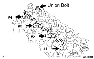
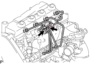
Tighten the 4 hollow screws from #1 to #4 in order.
- Torque:
- 16 N*m { 163 kgf*cm, 12 ft.*lbf }
-
Tighten the union bolt.
- Torque:
- 13 N*m { 130 kgf*cm, 9 ft.*lbf }
Note
In case of overtightening the nozzle leakage, replace it with a new one.
-
Remove the injection pipe No.1, No.2, No.3 and No.4.
-
-
CHECK NOZZLE LEAKAGE PIPE LEAK
-
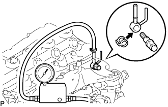
Using SST, install the nozzle leakage pipe No.2 and a new gasket.
- SST
- 09280-00010
- Torque:
- 21 N*m { 215 kgf*cm, 15 ft.*lbf }
Nozzle leakage pipe No.2 23762 - 27010 Gasket 90904 - 30012 -
Using SST (turbo charge pressure gauge), set the SST to the leakage pipe No.2 and maintain 250 kPa (2.5 kgf/cm2, 37 psi) of pressure for 60 seconds to check that there are no leaks from the nozzle leakage pipe assembly.
Note
Be sure to keep specified pressure, preventing form leakage.
Tech Tips
-
Apply a coat of engine oil to the nozzle leakage pipe assembly connection, and check that no bubbles come from the nozzle leakage pipe assembly.
-
Check that indication on the SST (turbo charger pressure gauge) does not go down while pressure is applied.
-
-
Remove the SST, nozzle leakage pipe assembly No.2.
-
-
INSTALL TIMING BELT COVER NO.2
-
Remove old seal packing (FIPG) from the timing gear case.
-
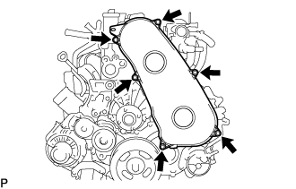
Apply seal packing to the specific places shown in the illustration.
Seal packing Toyota Genuine Seal Packing Black, Three Bond 1207B or equivalent Note
-
After applying FIPG, install the timing belt No.2 cover within 3 minutes and tighten its bolts and nuts within 15 minutes.
-
Do not start the engine 2 hours after the installation.
-
-
Fix the timing belt cover No.2 with the 4 bolts and nuts.
- Torque:
- 10 N*m { 102 kgf*cm, 7 ft.*lbf }
-
-
INSTALL TIMING BELT IDLER SUB-ASSEMBLY NO.1
-
Using a 10 mm socket hexagon wrench, install the new plate washer and timing belt idler No.1.
- Torque:
- 35 N*m { 357 kgf*cm, 26 ft.*lbf }
-
-
INSTALL CAMSHAFT TIMING PULLEY
-
Install the camshaft timing pulley.
-
Tighten the bolt for the camshaft timing pulley while holding the camshaft with a monkey wrench.
- Torque:
- 98 N*m { 1,000 kgf*cm, 72 ft.*lbf }
-
-
PISTON AND VALVE BREAKE PREVENT WORK
-
При повороте распредвала со снятым приводным ремнем газораспределения поверните коленчатый вал на 90° против часовой стрелки.
Note
При установке приводного ремня газораспределения поверните распредвал, чтобы совместить синхронизирующие метки, а затем поверните коленчатый вал по часовой стрелке и совместите синхронизирующие метки, как показано на рисунке.
-
-
INSTALL TIMING BELT
-
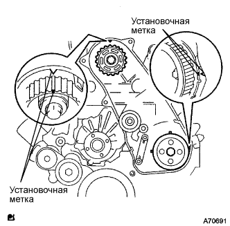
Удостоверьтесь, что установочные метки совмещены, как показано на рисунке.
-
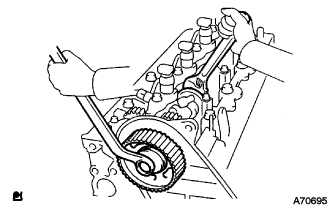
Установите приводной ремень газораспределения на шкив приводного вала насоса, зубчатое колесо распредвала и опорный ролик приводного ремня газораспределения № 1, придерживаясь этой последовательности.
-
Установите натяжитель вертикально на пресс.
Note
-
Не допускайте царапания и деформирования конца толкателя.
-
Запрессуйте толкатель натяжителя.
-
Обеспечьте защиту конца толкателя от повреждений ветошью.
-
-
С помощью пресса медленно запрессуйте толкатель с усилием 981 - 9807 Н (100 - 1000 кгс, 220 - 2205 фунт-силы).
Note
Не прикладывайте к толкателю усилие свыше 981 - 9807 Н (100 - 1000 кгс, 220 - 2205 фунт-силы).
-
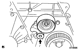
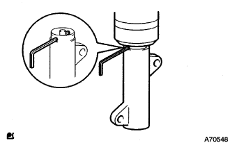
Совместите отверстия в толкателе и кожухе. Для сохранения положения установки толкателя пропустите через отверстия шестигранную головку на 1,27 мм.
-
Временно закрепите натяжитель приводного ремня 2 болтами, прижимая опорный ролик к приводному ремню газораспределения.
-
Затяните 2 болта.
- Torque:
- 13 Н*м { 133 кгс*см, 10 фунт-сила-футов }
Note
Равномерно затяните 2 болта и установите натяжитель
-
Выньте из натяжителя торцевой гаечный ключ на 1,5 мм.
-
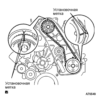
Поверните коленчатый вал по часовой стрелке на два оборота и убедитесь, что установочные метки совмещены, как показано на рисунке.
-
-
INSTALL TIMING BELT COVER NO.1
-
Установите крышку приводного ремня газораспределения № 1 и закрепите ее 6 болтами.
- Torque:
- 6,0 Н*м { 61 кгс*см, 53 фунт-сила-дюйма }
-
Присоедините зажим жгута проводов.
-
-
INSTALL CYLINDER HEAD COVER SUB-ASSEMBLY
-

Install 4 new No. 3 cylinder head cover gaskets to the cylinder head cover as shown in the illustration.
Note
-
Do not install the gaskets at an angle.
-
Keep the lip of the gasket free from foreign materials.
-
-
Install a new cylinder head cover gasket to the cylinder head cover.
-
Remove old seal packing (FIPG) from the cylinder head.
-
Apply a seal packing to the specific places described in the illustration.
Seal packing Toyota Genuine Seal Packing Black, Three Bond 1207B or equivalent Note
-
After applying the seal packing, parts must be assembled within 3 minutes, and then tighten within 15 minutes.
-
Otherwise the material must be removed and reapplied.
-
Do not start the engine 2 hour after the installation.
-
-
Install the cylinder head cover with 10 bolts and 2 nuts.
- Torque:
- 9.0 N*m { 92 kgf*cm, 80 in.*lbf }
-
Connect the ventilation hose.
-
Install a new nozzle holder seal.
-
-
INSTALL NOZZLE LEAKAGE PIPE ASSEMBLY NO.2
-
Temporarily install the nozzle leakage pipe assembly No.2 with the 2 bolts.
-
Install the check valve nozzle leakage pipe assembly No.2 and a new gasket.
- Torque:
- 21 N*m { 214 kgf*cm, 15 ft.*lbf }
-
Tighten the 2 bolts.
- Torque:
- 13 N*m { 133 kgf*cm, 10 ft.*lbf }
-
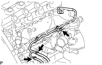
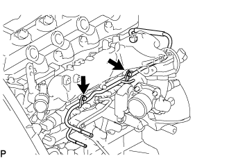
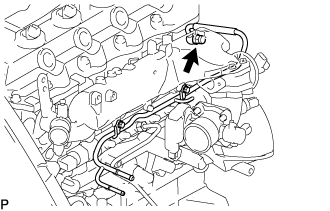
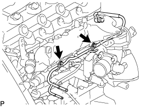
Install the 3 fuel hoses on the nozzle leakage pipe assembly No.2.
-
-
INSTALL FUEL INLET PIPE SUB-ASSEMBLY
Note
-
When replacing the fuel supply pump, common rail, cylinder block, cylinder head, cylinder head gasket, or timing gear case with a new one, replace the fuel inlet pipe.
-
Be careful not to adhere dusts, dirt or any other materials onto the joint area of the fuel inlet pipe.
-
Temporarily install the fuel inlet pipe.
-
Using SST, tighten the injection pipe on the common rail side.
- SST
- 09023-12701
- Torque:
- 32 N*m { 326 kgf*cm, 24 ft.*lbf, for use with SST }
-
Using SST, tighten the injection pipe on the supply pump side.
- SST
- 09023-12701
- Torque:
- 32 N*m { 326 kgf*cm, 24 ft.*lbf, for use with SST }
-
-
INSTALL INJECTION PIPE
- SST
- 09023-12701
Note
-
When replacing the fuel injector, common rail, or cylinder head with a new one, replace injection pipes No. 1, No. 2, No. 3, and No. 4.
-
Keep clean the joint of the injection pipe.
-
Install the injection pipes.
-
Temporarily install the 4 injection pipes.
-
Install the injection pipe clamp No.3 in 2 nuts.
- Torque:
- 5.0 N*m { 51 kgf*cm, 44 in.*lbf }
-
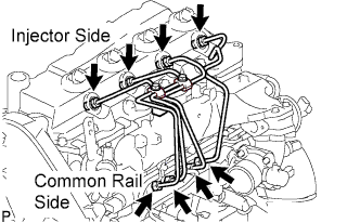
Fasten the union sequentially, from the injection pipe common rail to the injector, using SST.
- SST
- 09023-12701
- Torque:
- Use union nut wrench and torque wrench
- 32 N*m { 326 kgf*cm, 24 ft.*lbf }
-
-
INSTALL OIL LEVEL GAUGE GUIDE
-
Установите на трубку щупа проверки уровня масла новое уплотнительное кольцо.
-
Нанесите на уплотнительное кольцо тонкий слой моторного масла.
-
Установите трубку щупа проверки уровня масла и закрепите ее болтом.
- Torque:
- 8,0 Н*м { 82 кгс*см, 71 фунт-сила-дюйм }
-
Установите щуп проверки уровня масла.
-
-
INSTALL ELECTRIC EGR CONTROL VALVE ASSEMBLY (w/ EGR Valve)
-
REMOVE INTAKE AIR CONNECTOR (w/o EGR Valve)
-
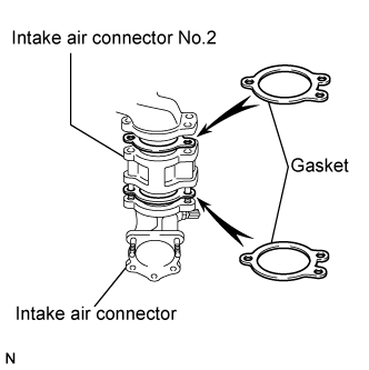
Temporarily install 2 new gaskets and intake air connector No.2 to the intake air connector.
-
Temporarily tighten the intake air connector assembly with the bolt and 2 nuts.
-
Tighten the manifold stay with the bolt.
-
Tighten the intake air connector with the bolt and 2 nuts.
-
Install the vacuum hose to the intake air connector.
-
-
INSTALL DIESEL THROTTLE BODY ASSEMBLY
-
INSTALL ENGINE SERVICE HOLE COVER NO.2
-
Install the engine service hole cover No.2 with the 3 bolts.
- Torque:
- 13 N*m { 133 kgf*cm, 10 ft.*lbf }
-
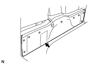
Return the carpet.
-
-
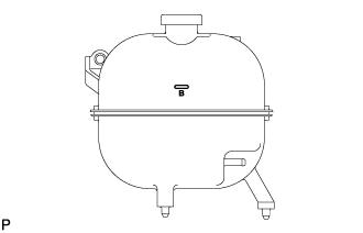
INSTALL VANE PUMP OIL RESERVOIR ASSEMBLY
-
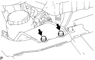
Установите масляный бачок лопастного насоса в сборе и закрепите 2 болтами.
- Torque:
- 8,0 Н*м { 82 кгс*см, 71 фунт-сила-дюйм }
-
-
CONNECT WATER BY-PASS HOSE NO.3
-
Подсоедините перепускной шланг охлаждающей жидкости № 3 хомутом к перепускному патрубку охлаждающей жидкости № 2.
-
-
CONNECT RADIATOR HOSE NO.4
-
Подсоедините шланг радиатора № 4 к отводящему патрубку охлаждающей жидкости и закрепите его хомутом.
-
-
CONNECT AIR HOSE NO.4
-
Подсоедините воздушный шланг № 4 хомутом к корпусу дроссельной заслонки.
-
-
CONNECT OIL RETURN HOSE (w/ Intercooler)
-
INSTALL TURBOCHARGER SUB-ASSEMBLY
-
INSTALL VENTILATION HOSE HEAT INSULATOR
-
Установите теплозащитный экран шланга вентиляции картера и закрепите его 2 болтами.
- Torque:
- 12 Н*м { 122 кгс*см, 9 фунт-сила-футов }
-
-
INSTALL VENTILATION PIPE
-
Установите вентиляционный патрубок и закрепите его болтом.
- Torque:
- 20 Н*м { 204 кгс*см, 15 фунт-сила-футов }
-
-
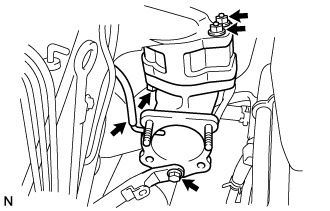
INSTALL COMPRESSOR BRACKET (w/ Air Conditioning System)
-
Временно установите кронштейн компрессора и закрепите его 4 болтами.
Tech Tips
Убедитесь, что кронштейн компрессора касается блока цилиндров.
-
Установите кронштейн компрессора, затянув 4 болта, как показано на рисунке.
- Torque:
- 45 Н*м { 459 кгс*см, 33 фунт-сила-фута }
-
-
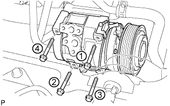
INSTALL COMPRESSOR AND MAGNETIC CLUTCH (w/ Air Conditioning System)
-
Предварительно закрепите компрессор и электромагнитную муфту 4 болтами.
-
Закрепите компрессор и электромагнитную муфту 4 болтами.
- Torque:
- 25 Н*м { 255 кгс*см, 18 фунт-сила-футов }
Note
При установке компрессора и электромагнитной муфты затягивайте болты в последовательности, показанной на рисунке.
-
-
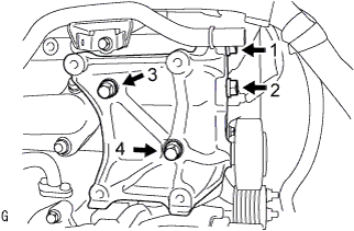
INSTALL COMPRESSOR OUTLET ELBOW
-
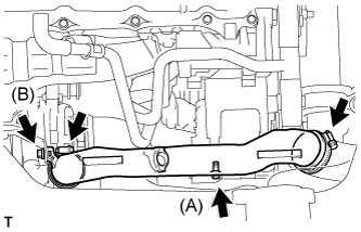
Install the compressor outlet elbow with the 2 bolts and 2 clamps.
- Torque:
- Bolt (A)
- 12 N*m { 122 kgf*cm, 9 ft.*lbf }
- Bolt (B)
- 32 N*m { 326 kgf*cm, 24 ft.*lbf }
-
-
INSTALL AIR CLEANER HOSE ASSEMBLY
-
Install the air cleaner hose assembly with the clamp.
-
-
INSTALL AIR TUBE ASSEMBLY
-
Install the air tube assembly with the 2 clamps and 2 bolts.
-
-
INSTALL FENDER APRON MUDGUARD SEAL RH
-
INSTALL EXHAUST PIPE ASSEMBLY FRONT
-
Установите пружину сжатия.
-
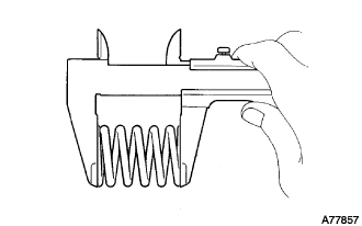
С помощью штангенциркуля измерьте длину пружин в свободном состоянии.
Минимально допустимая длина 40,5 мм (1,594 дюйма) Tech Tips
Если длина в свободном состоянии меньше минимально допустимой, замените пружину сжатия.
-
-
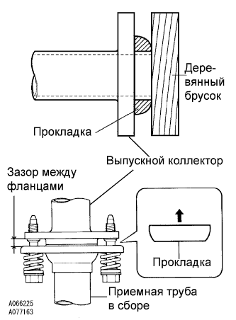
Установите прокладку.
-
Полностью вставьте рукой новую прокладку в выпускной коллектор.
-
Наденьте прокладку на выпускной коллектор с помощью деревянного бруска, равномерно распределяя удары.
Note
-
Правильно выберите направление установки прокладки.
-
Повторное использование прокладок запрещено.
-
Действуйте осторожно, чтобы не повредить прокладку.
-
Чтобы обеспечить хорошее уплотнение, не насаживайте прокладку на выпускной коллектор с помощью приемной трубы.
-
-
-
Подсоедините опору выпускной трубы, установите приемную трубу в сборе и новую прокладку и закрепите ее 4 болтами, 2 пружинами сжатия и 2 гайками.
- Torque:
- Со стороны выпускного коллектора
- 43 Н*м { 438 кгс*см, 32 фунт-сила-фута }
- Со стороны центральной выпускной трубы в сборе
- 48 Н*м { 489 кгс*см, 35 фунт-сила-футов }
Note
После установки убедитесь, что зазор между фланцами выпускного коллектора и приемной трубы приблизительно одинаков по всему периметру.
-
-
INSTALL FAN & GENERATOR V BELT
-
Провернув шкив натяжителя поликлинового ремня по часовой стрелке, установите поликлиновой ремень вентилятора и генератора.
Note
Проверьте правильность посадки поликлинового ремня вентилятора и генератора на каждом шкиве.
-
Проверьте метку индикатора натяжителя поликлинового ремня (см. стр. Click here).
-
-
INSTALL ENGINE SERVICE HOLE SUB COVER SUB-ASSEMBLY
-
Установите вспомогательную крышку технологического отверстия двигателя и закрепите ее 5 болтами.
- Torque:
- 13 Н*м { 133 кгс*см, 10 фунт-сила-футов }
-
-
INSTALL FRONT DOOR SCUFF PLATE RH
-
INSTALL FRONT SEAT ASSEMBLY RH (for Hi-back Seat Type)
-
Perform the same procedure as above on the opposite side. Click here
-
-
INSTALL FRONT SEAT ASSEMBLY RH (for Low-back Seat Type)
-
Perform the same procedure as above on the opposite side. Click here
-
-
CONNECT BATTERY NEGATIVE TERMINAL
-
ADD ENGINE COOLANT
-
Надежно затяните сливные пробки.
-
Залейте охлаждающую жидкость в расширительный бачок радиатора до верха горловины.
Номинальный объем Параметр / Устройство Заданные условия Для моделей без подогревателя 13,2 литра (13,9 кварты США, 11,6 английской кварты) Для моделей с передним подогревателем 14,2 литра (15,0 кварты США, 12,5 английской кварты) Для моделей с передним и задним подогревателями 16,2 л (17,1 кварты США, 14,3 английской кварты) Note
Не доливайте простую воду вместо охлаждающей жидкости двигателя.
Tech Tips
-
Использование неподходящей охлаждающей жидкости может привести к повреждению системы охлаждения двигателя.
-
Разрешается использовать только охлаждающую жидкость "TOYOTA Super Long Life Coolant" или аналогичную высококачественную охлаждающую жидкость на основе этиленгликоля (а не на силикатной, аминовой, нитритной или борнокислой основе), изготовленную по гибридной технологии органических кислот с длительным сроком годности (охлаждающая жидкость, изготовленная по гибридной технологии органических кислот, состоит из низкофосфатных соединений и органических кислот).
-
-
Ослабьте прокачной штуцер корпуса отводящего патрубка.
-
После удаления воздуха и слива охлаждающей жидкости двигателя надежно затяните прокачной штуцер.
- Torque:
- 8,0 Н*м { 82 кгс*см, 71 фунт-сила-дюйм }
-
Долейте охлаждающую жидкость в расширительный бачок радиатора до отметки B и установите пробку расширительного бачка радиатора.
-
Прогревайте двигатель, пока не откроется термостат.
-
Когда термостат откроется, несколько минут прокачивайте охлаждающую жидкость двигателя.
Tech Tips
Время открывания термостата можно проверить, сжав шланг радиатора № 3 рукой и определив, когда охлаждающая жидкость начинает поступать в шланг.
-
-
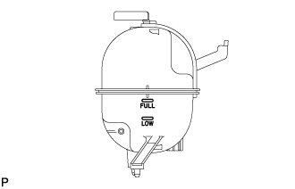
После охлаждения двигателя убедитесь, что уровень охлаждающей жидкости двигателя находится между отметками "LOW" и "FULL".
-
-
BLEED FUEL LINE
-
Move the priming pump in the upper part of the fuel filter assembly up and down, and fill the injection pump assembly and fuel system with fuel.
-
-
CHECK FUEL LEAK
-
PERFORM ACTIVE TEST
-
Connect the GTS to the DLC3.
-
Turn the ignition switch on.
-
Turn the GTS on.
-
Enter the following menus: Powertrain / Engine and ECT / Active Test.
-
Perform the Active Test.
Tester Display Test Details Control Range Diagnostic Notes Test the Fuel Leak Pressurizes common rail internal fuel pressure, and checks for fuel leaks Stop/Start
-
Fuel pressure inside common rail pressurized to specified value and engine speed increased to 2,000 rpm when ON is selected
-
Above conditions preserved while test is ON
-
-
-
-
CHECK FOR ENGINE OIL LEAKS
-
CHECK FOR ENGINE COOLANT LEAKS
CAUTION:
Не снимайте пробку радиатора, пока двигатель и радиатор не остынут. Выброс горячей охлаждающей жидкости и пара под давлением может стать причиной серьезных ожогов.
-
Заполните радиатор охлаждающей жидкостью и подсоедините к радиатору приспособление для опрессовки системы охлаждения и проверки пробки радиатора.
-
Прогрейте двигатель.
-
С помощью приспособления для опрессовки системы охлаждения и проверки пробки радиатора увеличьте давление в радиаторе до 137 кПа (1,4 кгс/см2, 19,9 фунтов на кв. дюйм) и убедитесь, что давление не падает.
Tech Tips
Если давление снижается, проверьте на наличие утечек шланги, радиатор и насос системы охлаждения. При отсутствии внешних утечек проверьте сердцевину отопителя, блок цилиндров и головку блока цилиндров.
-
-
CHECK EXHAUST LEAKAGE
-
INSTALL ENGINE UNDER COVER NO.1 (w/ Engine Under Cover No.1)
- Torque:
- 13 N*m { 133 kgf*cm, 10 ft.*lbf }
-
CHECK IDLE SPEED
Note
This checking procedure should be done under the following condition.
Tech Tips
-
Regarding the details about the intelligent tester, refer to its operator's manual.
-
If the intelligent tester is not available, a tachometer's tester probe can substitute for it.
-
Connect the intelligent tester to the DLC3.
-
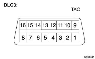
If the tester is not available, connect a tester probe of a tachometer to terminal 9 (TAC) of the DLC3 with SST.
- SST
- 09843-18030
-
Start the engine and check the idle speed.
Idle speed 700 to 800 rpm Tech Tips
If the idle speed is not as specified, check by troubleshooting in the diagnostics section.
-
In case of the tester probe of the tachometer is connected to the DLC3, disconnect the tester probe from terminal 9 of the DLC3 with SST.
-
Disconnect the intelligent tester from the DLC3.
-
-
INSPECT MAXIMUM ENGINE SPEED
Note
This checking procedure should be done under the following condition.
Tech Tips
-
Regarding the details about the intelligent tester, refer to its operator's manual.
-
If the intelligent tester is not available, a tachometer's tester probe can substitute for it.
-
Connect the intelligent tester to the DLC3.
-
If the tester is not available, connect a tester probe of a tachometer to terminal 9 (TAC) of the DLC3 with SST.
- SST
- 09843-18030
-
Start the engine.
-
Depress the accelerator pedal all the way to the limit.
-
Check the maximum speed.
Maximum speed 4500 to 4700 rpm Tech Tips
If the maximum speed is not as specified, check by troubleshooting in the diagnostics section.
-
In case of the tester probe of the tachometer is connected to the DLC3, disconnect the tester probe from terminal 9 of the DLC3 with SST.
-
Disconnect the intelligent tester from the DLC3.
-
-
CHECK FUNCTION OF THROTTLE BODY
-
Inspect the throttle control motor.
-
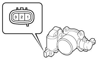
Using an ohmmeter, measure the resistance between the terminals.
Standard resistance Tester Connection Specified Condition 1 (DUTY) - Body ground Infinity
-
-
-
PERFORM INITIALIZATION