ГОЛОВКА БЛОКА ЦИЛИНДРОВ СНЯТИЕ

-
SEPARATE BATTERY NEGATIVE TERMINAL
-
REMOVE ENGINE UNDER COVER NO.1 (w/ Engine Under Cover No.1)
-
DRAIN ENGINE COOLANT
CAUTION:
Не снимайте пробку расширительного бачка радиатора, пока двигатель и радиатор не остынут. Выброс горячей охлаждающей жидкости и пара под давлением может стать причиной серьезных ожогов.
-
Ослабьте пробку сливного крана радиатора.
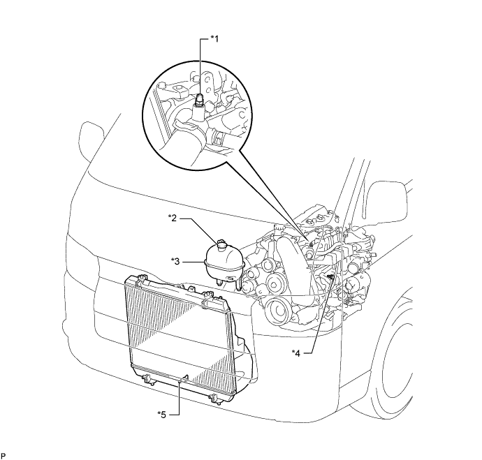
Обозначения на рисунке *1 Прокачной штуцер *2 Пробка расширительного бачка радиатора *3 Расширительный бачок радиатора в сборе *4 Пробка сливного крана блока цилиндров *5 Пробка сливного крана радиатора - - -
Снимите пробку расширительного бачка радиатора.
-
Ослабьте пробку сливного крана блока цилиндров (на крышке масляного радиатора двигателя) и слейте охлаждающую жидкость двигателя.
-
Затяните пробку сливного крана радиатора.
-
Затяните пробку крана сливного отверстия блока цилиндров (на крышке масляного радиатора двигателя).
- Torque:
- 8,0 Н*м { 82 кгс*см, 71 фунт-сила-дюйм }
-
-
REMOVE FRONT SEAT ASSEMBLY RH (for Hi-back Seat Type)
-
Perform the same procedure as above on the opposite side. Click here
-
-
REMOVE FRONT SEAT ASSEMBLY RH (for Low-back Seat Type)
-
Perform the same procedure as above on the opposite side. Click here
-
-
REMOVE FRONT DOOR SCUFF PLATE RH
-
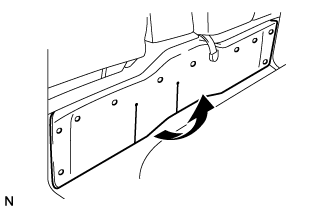
REMOVE ENGINE SERVICE HOLE SUB COVER SUB-ASSEMBLY
-
Заверните коврик и снимите вспомогательную крышку технологического отверстия двигателя.
-
-
REMOVE FAN & GENERATOR V BELT
-
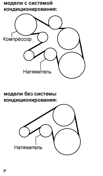
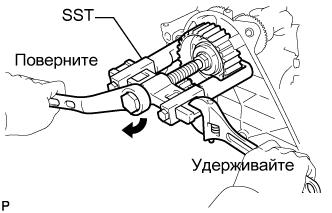
Снимите приводной ремень, повернув шкив натяжителя по часовой стрелке с помощью установочного болта шкива, чтобы ослабить натяжение ремня.
-
-
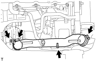
REMOVE EXHAUST PIPE ASSEMBLY FRONT
-
Выверните 4 болта, отверните 2 гайки и снимите 2 пружины сжатия. Снимите приемную трубу в сборе и 2 прокладки.
-
Отсоедините опору выпускной трубы и снимите приемную трубу в сборе и 2 прокладки.
-
-
REMOVE FENDER APRON MUDGUARD SEAL RH
-
REMOVE AIR TUBE ASSEMBLY
-
Remove the 2 clamps, 2 bolts and air tube assembly.
-
-
REMOVE AIR CLEANER HOSE ASSEMBLY
-
Remove the bolt and air cleaner hose assembly.
-
-
REMOVE COMPRESSOR OUTLET ELBOW
-
Remove the 2 bolts and 2 clamps, then remove the compressor outlet elbow.
-
-
SEPARATE COMPRESSOR AND MAGNETIC CLUTCH (w/ Air Conditioning System)
-
Отсоедините разъем.
-
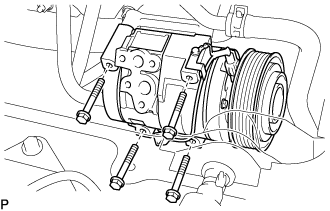
Выверните 4 болта и снимите компрессор и электромагнитную муфту.
-
-
REMOVE COMPRESSOR BRACKET
-
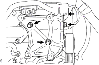
Выверните 4 болта и снимите кронштейн компрессора.
-
-
REMOVE VENTILATION PIPE
-
Выверните болт и снимите вентиляционный патрубок.
-
-
REMOVE VENTILATION HOSE HEAT INSULATOR
-
Выверните 2 болта и снимите теплозащитный экран шланга вентиляции картера.
-
-
REMOVE TURBOCHARGER SUB-ASSEMBLY
-
DISCONNECT OIL RETURN HOSE (w/ Intercooler)
-
DISCONNECT AIR HOSE NO.4
-
Снимите хомут и отсоедините воздушный шланг № 4 от корпуса дроссельной заслонки.
-
-
DISCONNECT RADIATOR HOSE NO.4
-
Снимите хомут и отсоедините шланг радиатора № 4 от отводящего патрубка охлаждающей жидкости.
-
-
DISCONNECT WATER BY-PASS HOSE NO.3
-
Снимите хомут и отсоедините перепускной шланг охлаждающей жидкости № 3 от перепускного патрубка охлаждающей жидкости.
-
-
SEPARATE VANE PUMP OIL RESERVOIR ASSEMBLY
-
Выверните 2 болта и отсоедините масляный бачок лопастного насоса в сборе.
Note
Подвесьте масляный бачок лопастного насоса в сборе с помощью провода, чтобы не допустить пролива жидкости для механизма рулевого управления с усилителем.
-
-
REMOVE TIMING BELT COVER NO.1
-
Remove the wire harness clamp.
-
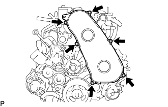
Remove the 6 bolts and timing belt cover No.1.
-
-
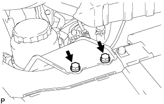
REMOVE ENGINE SERVICE HOLE COVER NO.2
-
Roll up the carpet.
-
Remove the 3 bolts and the engine service hole cover No.2.
-
-
REMOVE DIESEL THROTTLE BODY ASSEMBLY
-
REMOVE INTAKE AIR CONNECTOR (w/o EGR Valve)
-
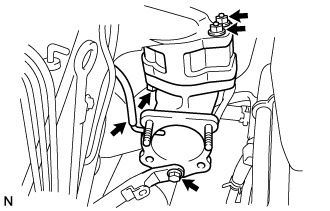
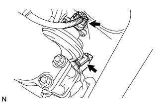
Remove the bolt, and separate the manifold stay.
-
Disconnect the vacuum hose from intake air connector.
-
Remove the bolt, 2 nuts and the intake air connector assembly.
-
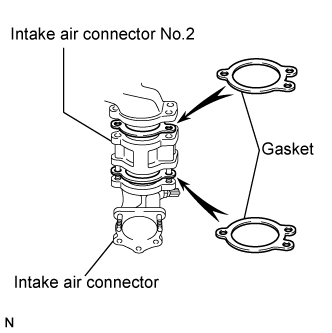
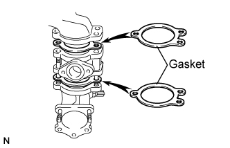
Remove the 2 gaskets and intake air connector No.2 from the intake air connector.
-
-
REMOVE ELECTRIC EGR CONTROL VALVE ASSEMBLY (w/ EGR Valve)
-
Remove the vacuum regulating valve.
-
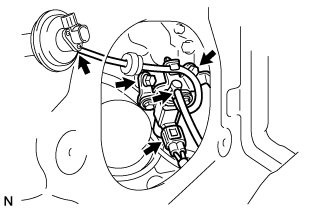
Remove the 2 vacuum hoses and the vacuum regulating valve connector.
-
Remove the 2 bolts and the vacuum regulating valve.
-
-
Remove the EGR valve assembly with the sensor.
-
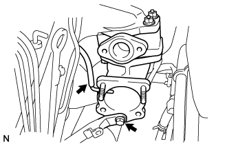
Remove the bolt, and separate the manifold stay.
-
Disconnect the vacuum hose from the intake air connector.
-
Disconnect the intake air temperature sensor connector.
-
Disconnect the EGR valve position sensor connector.
-
Remove the bolt, 2 nuts and the intake air connector assembly.
-
Remove the 2 gaskets and EGR valve assembly from the intake air connector.
-
-
-
REMOVE OIL LEVEL GAUGE GUIDE
-
Снимите щуп проверки уровня масла.
-
Выверните болт и снимите трубку щупа проверки уровня масла.
-
-
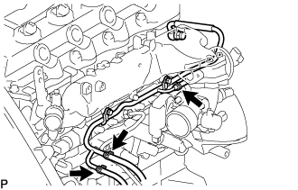
REMOVE INJECTION PIPE
- SST
- 09023-12701
-
Remove the injection pipe.
-
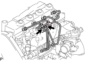
Remove the 2 nuts and injection pipe clamp No.3.
-
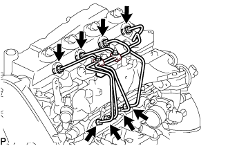
Using SST, remove the 4 injection pipes.
- SST
- 09023-12701
-
-
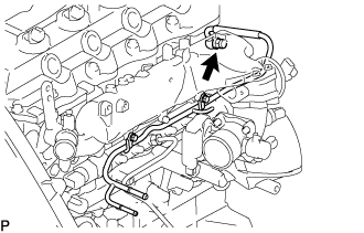
REMOVE FUEL INLET PIPE SUB-ASSEMBLY
-
Using SST, remove the fuel inlet pipe sub-assembly.
- SST
- 09023-12701
-
-
REMOVE NOZZLE LEAKAGE PIPE ASSEMBLY NO.2
-
Disconnect 3 fuel hoses from nozzle leakage pipe assembly No.2.
-
Remove the union bolt from nozzle leakage pipe No.2.
-
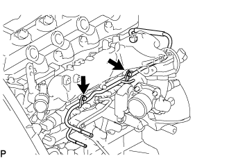
Remove the 2 bolts and nozzle leakage pipe No.2.
-
Remove the gasket from nozzle leakage pipe No.2.
-
-
REMOVE CYLINDER HEAD COVER SUB-ASSEMBLY
-
Using a small screwdriver, remove the holder seal by prying the portion between the holder seal and the cutout part of the cylinder head.
-
Disconnect the ventilation hose.
-
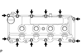
Remove the 10 bolts, 2 nuts, cylinder head cover and the cylinder head cover gasket.
Note
After removing the fuel pipe, put a plastic bag and rubber band to prevent dirt and foreign objects over the injectors inlet.
-
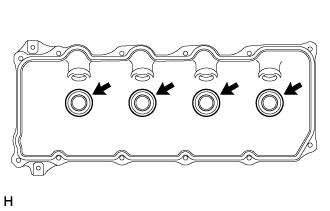
Remove the 4 No. 3 cylinder head cover gaskets from the cylinder head cover.
-
-
SET NO.1 CYLINDER TO TDC/ COMPRESSION
-
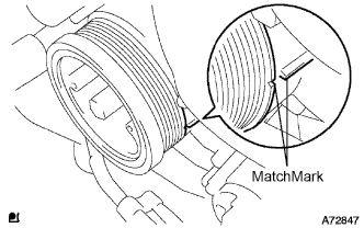
Align the matchmarks of the crankshaft pulley and timing gear case cover by rotating the crankshaft in clockwise direction.
Tech Tips
Make sure that both camnoses on the intake side and exhaust side of the cylinder No.1 face upward.
-
-
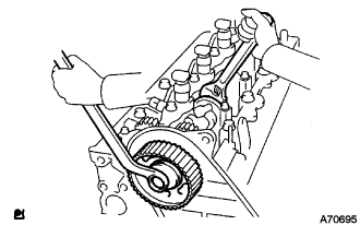
REMOVE TIMING BELT
-
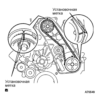
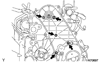
Turn the crankshaft in the clockwise direction and align the timing marks as shown in the illustration.
-
Uniformly loosen the 2 bolts, and remove the chain tensioner assembly No.1.
-
Remove the timing belt.
-
-
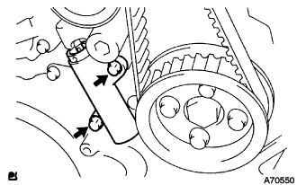
REMOVE CAMSHAFT TIMING PULLEY
-
Remove the bolt for the camshaft timing pulley while holding the camshaft with a monkey wrench.
-
Using SST, remove the camshaft timing pulley.
- SST
- 09950-40011 ( 09951-04010, 09952-04010, 09953-05010, 09957-04010 )
- 09955-04150
-
-
REMOVE TIMING BELT IDLER SUB-ASSEMBLY NO.1
-
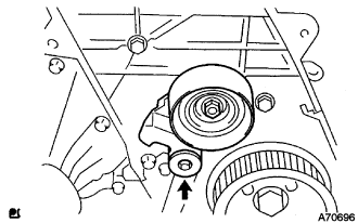
Using a 10 mm socket hexagonal wrench remove the timing belt idler No.1.
-
-
REMOVE TIMING BELT COVER NO.2
-
Remove the 4 bolts and nuts, then remove the timing belt No.2 cover.
-
-
REMOVE INJECTOR ASSEMBLY
-
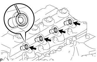
REMOVE CAMSHAFT
-
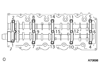
Uniformly loosen and remove the 15 camshaft bearing cap bolts in the specified order described in the illustration.
-
Remove the 5 camshaft bearing caps.
-
Pull out the oil seal.
-
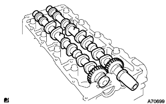
Remove the camshaft and No.2 camshaft.
Note
-
Do not pry the camshaft.
-
Do not damage the thrusts of the cylinder head.
-
-
-
REMOVE CYLINDER HEAD SUB-ASSEMBLY
-
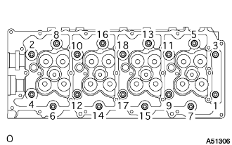
Loosen the cylinder head bolts equally and gradually in the order shown in the illustration to remove the bolt and washers.
-
-
REMOVE CYLINDER HEAD GASKET
-
INSPECT CYLINDER HEAD SET BOLT
-
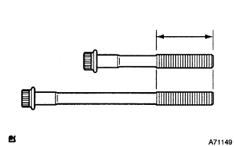
Using vernier calipers, measure the outer diameter within the specified area shown in the illustration.
Standard outer diameter 11.76 to 11.97 mm (0.463 to 0.471 in.) Minimum outer diameter 11.60 mm (0.457 in.) Tech Tips
Measure the diameter at several locations within the specified area, and replace the bolt with a new one if a result value would be less than the minimum diameter value.
-