- Click here
INSTALL STRAIGHT PIN
Note:It is not necessary to remove the straight pin unless it is being replaced.
-
for Timing Chain Cover Sub-assembly Side:
-
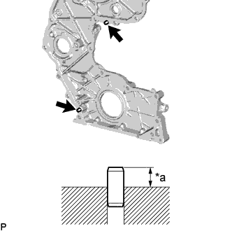
Using a plastic-faced hammer, tap in 2 new straight pins to the timing chain cover sub-assembly.
Standard protrusion height 5.0 to 7.0 mm (0.197 to 0.276 in.) Table 1. Text in Illustration *a Protrusion Height
-
-
for Timing Chain Case Assembly Side:
-
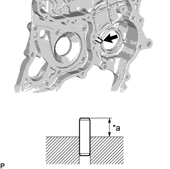
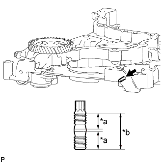
Using a plastic-faced hammer, tap in a new straight pin to the timing chain case assembly.
Standard protrusion height 18 to 20 mm (0.709 to 0.787 in.) Table 2. Text in Illustration *a Protrusion Height
-
-
- Click here
INSTALL STUD BOLT
Note:If a stud bolt is deformed or its threads are damaged, replace it.
-
for Timing Chain Cover Sub-assembly Side:
-
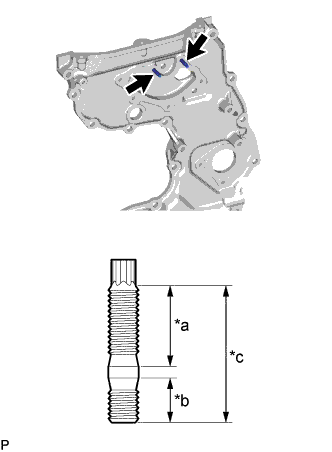
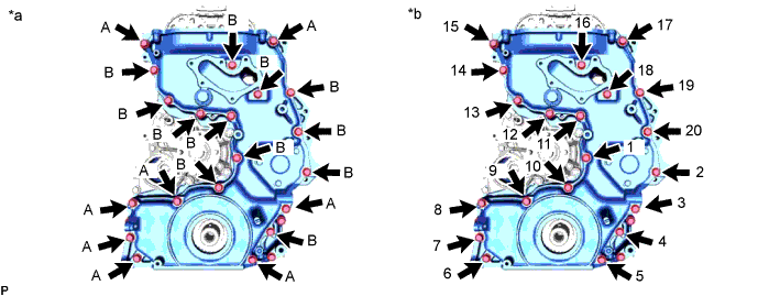
Using an E6 "TORX" socket wrench, install the stud bolts to the timing chain cover sub-assembly.
6.0 N*m 61 kgf*cm 53 in.*lbf Table 3. Text in Illustration *a 16 mm (0.630 in.) *b 9.0 mm (0.354 in.) *c 27 mm (1.06 in.)
-
-
for Timing Chain Case Assembly Side:
-
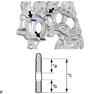
Using an E8 "TORX" socket wrench, install the stud bolts to the timing chain case assembly.
10 N*m 102 kgf*cm 7 ft.*lbf Table 4. Text in Illustration *a 19 mm (0.748 in.) *b 16 mm (0.630 in.) *c 44 mm (1.73 in.)
-
-
Using an E6 "TORX" socket wrench, install the stud bolt to the timing chain case assembly.
6.0 N*m 61 kgf*cm 53 in.*lbf Table 5. Text in Illustration *a 9.0 mm (0.354 in.) *b 19 mm (0.748 in.)
-
- Click here
INSTALL LOCK PLATE
-
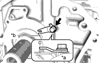
Install the lock plate to the cylinder block sub-assembly with the bolt.
10 N*m 102 kgf*cm 7 ft.*lbf Table 6. Text in Illustration *a Cylinder Block Sub-assembly Side *b Oil Jet Tip:
-
Make sure the lock plate is facing the direction shown in the illustration.
-
Make sure the end of the lock plate is holding the oil jet as shown in the illustration.
-
-
- Click here
INSTALL CYLINDER HEAD GASKET
-
Check the piston protrusions for each cylinder.
-
Clean the cylinder block sub-assembly with solvent.
-
Set the piston of the cylinder to be measured to slightly before TDC.
-
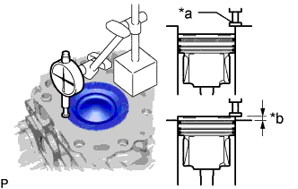
Place a dial indicator on the cylinder block sub-assembly, and position the measuring tip as shown in the illustration.
Table 7. Text in Illustration *a Measuring Tip *b Protrusion -
Set the dial indicator at 0 mm (0 in.)
Tip:Make sure that the measuring tip is square to the cylinder block gasket surface and piston head when taking the measurements.
-
-
Find where the piston head protrudes most by slowly turning the crankshaft clockwise and counterclockwise.
-
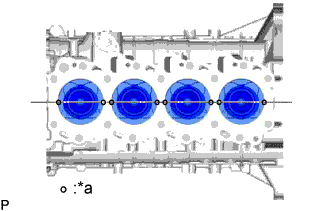
Measure the piston protrusion of each cylinder at the 2 points shown in the illustration.
Table 8. Text in Illustration *a Measuring Point -
For the piston protrusion value of each cylinder, use the average of the 2 measurements of each cylinder.
Standard piston protrusion 0.355 to 0.605 mm (0.0140 to 0.0238 in.) Tip:When installing the piston and connecting rod assembly, if the protrusion is not as specified, remove the piston and connecting rod assembly and reinstall them.
-
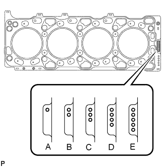
Select a new cylinder head gasket.
Tip:New cylinder head gaskets are available in 5 sizes, and are marked A, B, C, D or E.
Table 9. New Cylinder Head Gasket Thickness Mark Specified Condition A 1.15 to 1.25 mm (0.0453 to 0.0492 in.) B 1.20 to 1.30 mm (0.0472 to 0.0512 in.) C 1.25 to 1.35 mm (0.0492 to 0.0531 in.) D 1.30 to 1.40 mm (0.0512 to 0.0551 in.) E 1.35 to 1.45 mm (0.0531 to 0.0571 in.)
-
Select the largest piston protrusion value from the measurements made. Then select a new appropriate cylinder head gasket according to the table below.
Table 10. Gasket Size Item Specified Condition Piston protrusion 0.355 to 0.405 mm (0.0140 to 0.0159 in.) 0.405 to 0.455 mm (0.0159 to 0.0179 in.) 0.455 to 0.505 mm (0.0179 to 0.0199 in.) 0.505 to 0.555 mm (0.0199 to 0.0219 in.) 0.555 to 0.605 mm (0.0219 to 0.0238 in.) Gasket to be used A B C D E
-
-
Clean and degrease the contact surfaces of the cylinder head sub-assembly and cylinder block sub-assembly.
-
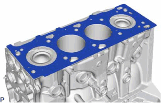
Place the cylinder head gasket on the cylinder block sub-assembly.
Note:Make sure the cylinder head gasket is installed facing the proper direction.
-
- Click here
INSTALL CYLINDER HEAD SUB-ASSEMBLY
Tip:
-
If any cylinder head set bolt is broken or deformed, replace the cylinder head set bolt and cylinder head set bolt spacer.
-
The cylinder head set bolts are tightened in 3 progressive steps.
-
Place the cylinder head sub-assembly on the cylinder head gasket.
-
Apply a light coat of engine oil to the threads and under the heads of the cylinder head set bolts.
-
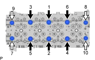
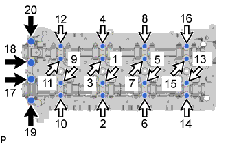
Install and uniformly tighten the 10 cylinder head set bolts and 6 cylinder head set bolt spacers in several passes in the sequence shown in the illustration.
for bolt A 150 N*m 1530 kgf*cm 111 ft.*lbf for bolt B 85 N*m 867 kgf*cm 63 ft.*lbf Item Specified Condition Bolt A 180 mm (7.09 in.) Bolt B 127 mm (5.00 in.) Table 11. Text in Illustration 
Bolt A 
Bolt B
-
If any of the cylinder head set bolts does not meet the specification, replace it.
-
-
Mark the front of each cylinder head set bolt with paint.
-
Further tighten the cylinder head set bolts by 90° in the sequence shown in the illustration above.
-
Finally, tighten the cylinder head set bolts by an additional 90°.
-
Check that the painted marks are now facing rearward.
-
- Click here
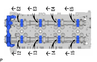
INSTALL VALVE LASH ADJUSTER ASSEMBLY
-
Install the 16 valve lash adjuster assemblies to the cylinder head sub-assembly.
-
- Click here
INSTALL NO. 1 VALVE ROCKER ARM SUB-ASSEMBLY
-
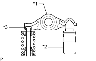
Check that the No. 1 valve rocker arm sub-assembly is firmly set to the valve lash adjuster assembly.
Table 12. Text in Illustration *1 No. 1 Valve Rocker Arm Sub-assembly *2 Valve Stem Cap *3 Valve Lash Adjuster Assembly -
Apply a light coat of engine oil to the camshaft journals of the cylinder head sub-assembly and the thrust portion of the camshaft.
-
Install the 16 No. 1 valve rocker arm sub-assemblies to the 16 valve lash adjuster assemblies.
-
- Click here
INSTALL NO. 2 CAMSHAFT
Tip: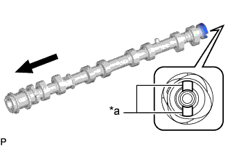
The groove is at the rear end of the No. 2 camshaft.
Table 13. Text in Illustration *a Groove Engine Front Side
-
Clean the No. 2 camshaft journals.
-
Apply a light coat of engine oil to the No. 2 camshaft journals of the cylinder head sub-assembly and the thrust portion of the No. 2 camshaft.
-
- Click here
INSTALL CAMSHAFT
-
Clean the camshaft journals.
-
Apply a light coat of engine oil to the camshaft journals of the cylinder head sub-assembly and the thrust portion of the camshaft.
-
Make sure the knock pins of the camshaft and No. 2 camshaft are facing the direction shown in the illustration.
Table 14. Text in Illustration *a Knock Pin
-
- Click here
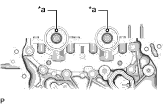
INSTALL NO. 1 AND NO. 2 CAMSHAFT BEARING CAP
-
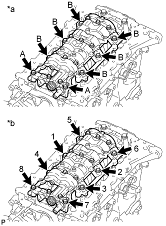
Set the No. 1 camshaft bearing cap and 8 No. 2 camshaft bearing caps to the cylinder head sub-assembly as shown in the illustration.
-
Temporarily install the 20 camshaft bearing cap bolts.
-
Uniformly tighten the 20 camshaft bearing cap bolts in several steps in the order shown in the illustration.
for camshaft bearing cap bolt A (No. 1 camshaft bearing) 21 N*m 214 kgf*cm 15 ft.*lbf for camshaft bearing cap bolt B (No. 2 camshaft bearing) 10 N*m 102 kgf*cm 7 ft.*lbf Table 15. Text in Illustration Camshaft Bearing Cap Bolt A Camshaft Bearing Cap Bolt B
-
- Click here
INSTALL NO. 3 CAMSHAFT BEARING CAP
-
Clean and degrease the contact surfaces of the No. 3 camshaft bearing cap and cylinder head sub-assembly.
-
Apply seal packing to the No. 3 camshaft bearing cap in the areas indicated in the illustration.
Seal packing Toyota Genuine Seal Packing Black, Three Bond 1207B or equivalent Standard seal diameter 3.0 mm (0.118 in.) Table 16. Text in Illustration *a Engine Front Side 
Seal Packing Application Area Note:
-
Install the No. 3 camshaft bearing cap within 3 minutes and tighten the camshaft bearing cap bolts within 10 minutes after applying seal packing.
-
Do not add engine oil within 2 hours of installation.
-
Do not start the engine for at least 2 hours after the installation.
-
-
Install the No. 3 camshaft bearing cap to the cylinder head sub-assembly with the 2 camshaft bearing cap bolts.
21 N*m 214 kgf*cm 15 ft.*lbf -
Wipe off excess seal packing from between the No. 3 camshaft bearing cap and cylinder head sub-assembly.
-
- Click here
INSTALL TIMING CHAIN CASE ASSEMBLY AND ENGINE WATER PUMP ASSEMBLY
-
Install a new No. 2 water pump gasket.
-
Install the 4 O-rings to the cylinder block sub-assembly and cylinder head sub-assembly.
-
Clean and degrease the contact surfaces of the timing chain case assembly, cylinder head sub-assembly and cylinder block sub-assembly.
-
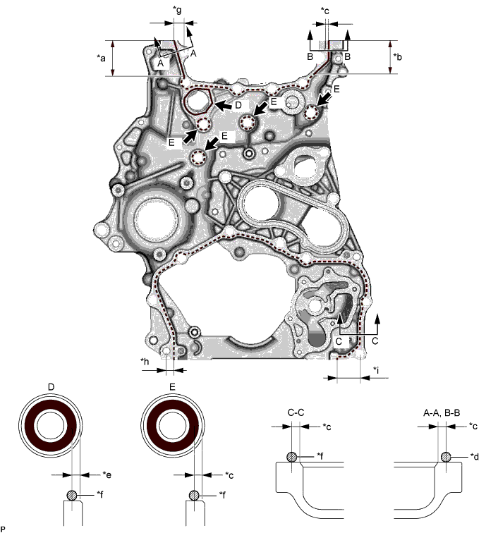
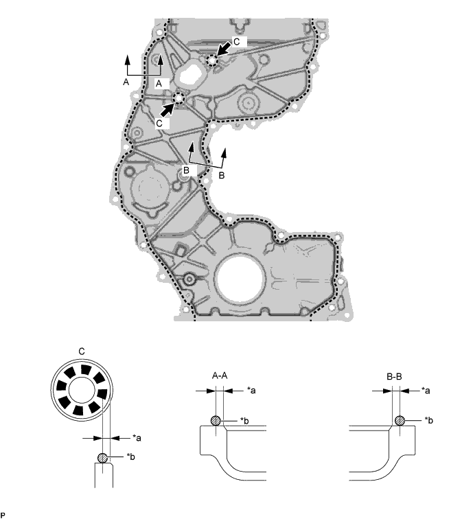
Apply a coating of seal packing to the timing chain case assembly at the points shown in the illustration.
Table 17. Text in Illustration *a 46 mm (1.81 in.) *b 50 mm (1.97 in.) *c 2.0 to 3.0 mm (0.0787 to 0.118 in.) *d 2.5 to 3.5 mm (0.0984 to 0.138 in.) *e 3.0 to 4.0 mm (0.118 to 0.158 in.) *f 1.5 to 2.5 mm (0.0591 to 0.0984 in.) *g 13 to 15 mm (0.512 to 0.591 in.) *h 9.0 to 11 mm (0.354 to 0.433 in.) *i 31 to 33 mm (1.22 to 1.30 in.) - - Seal packing for line area D Toyota Genuine Seal Packing 1282B, Three Bond 1282B or equivalent. for line area A-A, B-B, C-C and E Toyota Genuine Seal Packing Black, Three Bond 1207B or equivalent. Line Type and Area Seal Packing Diameter Application Area Seal Packing Application Length Dashed Line 1.5 to 2.5 mm (0.0591 to 0.0984 in.) 2.0 to 3.0 mm (0.0787 to 0.118 in.) - A - A 2.5 to 3.5 mm (0.0984 to 0.138 in.) 2.0 to 3.0 mm (0.0787 to 0.118 in.) 46 mm (1.81 in.) B - B 2.5 to 3.5 mm (0.0984 to 0.138 in.) 2.0 to 3.0 mm (0.0787 to 0.118 in.) 50 mm (1.97 in.) D 1.5 to 2.5 mm (0.0591 to 0.0984 in.) 3.0 to 4.0 mm (0.118 to 0.158 in.) - Note:
-
Using non-residue solvent, clean and remove any oil from the installation surface.
-
Install the part within 3 minutes and tighten the bolts within 10 minutes after applying seal packing.
-
Do not add engine oil for at least 2 hours after installation.
-
Do not start the engine within 2 hours after installation.
-
-
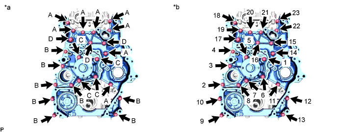
Temporarily install the timing chain case assembly with the 15 bolts.
Table 18. Text in Illustration *a Type of bolt *b Tightening Bolt Length Item Length Thread Diameter Bolt A 30 mm (1.18 in.) 8.0 mm (0.315 in.) Bolt B 45 mm (1.77 in.) 8.0 mm (0.315 in.) Bolt C 65 mm (2.56 in.) 8.0 mm (0.315 in.) Bolt D 30 mm (1.18 in.) 10 mm (0.394 in.) -
Temporarily install a new gasket and the engine water pump assembly with the 8 bolts.
-
Tighten the 23 bolts in the order shown in the illustration.
for bolt A, B and C 25 N*m 255 kgf*cm 18 ft.*lbf for bolt D 43 N*m 438 kgf*cm 32 ft.*lbf Note:Check the torque of bolt 1 after tightening bolt 23.
-
- Click here
INSTALL INJECTION PUMP INSULATOR
-
Install the injection pump insulator to the cylinder block sub-assembly.
-
- Click here
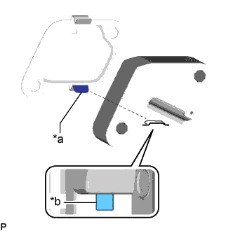
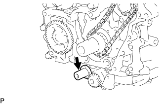
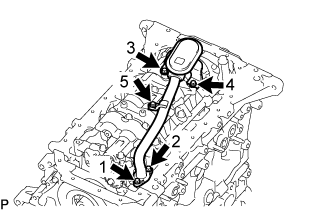
INSTALL SUPPLY PUMP ASSEMBLY
Note: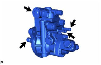
Do not hold the supply pump assembly by the parts indicated by the arrows in the illustration.
-
Install a new O-ring to the supply pump assembly.
-
Install the supply pump assembly to the timing chain case assembly with the 3 nuts.
21 N*m 214 kgf*cm 15 ft.*lbf -
Install the No. 1 fuel pump bracket to the cylinder block sub-assembly and supply pump assembly with the 2 bolts.
21 N*m 214 kgf*cm 15 ft.*lbf
-
- Click here
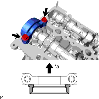
INSTALL NO. 1 CHAIN TENSIONER SLIPPER
-
Install the No. 1 chain tensioner slipper to the straight pin.
-
- Click here
TEMPORARILY INSTALL NO. 1 CHAIN VIBRATION DAMPER
-
Temporarily install the No. 1 chain vibration damper to the cylinder block sub-assembly with the bolt.
-
- Click here
INSTALL CRANKSHAFT TIMING SPROCKET, INJECTION PUMP DRIVE GEAR WITH NO. 1 CHAIN SUB-ASSEMBLY
-
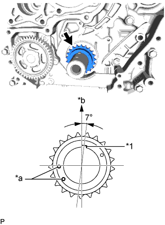
Install the crankshaft timing sprocket to the crankshaft.
Table 19. Text in Illustration *1 Crankshaft Pulley Set Key *a Timing Mark *b Upper Side -
Align the crankshaft pulley set key as shown in the illustration.
-
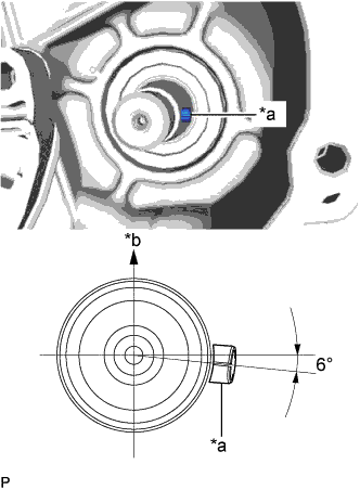
Align the supply pump shaft key as shown in the illustration.
Table 20. Text in Illustration *a Supply Pump Shaft Key *b Upper Side -
Remove the crankshaft timing sprocket from the crankshaft.
-
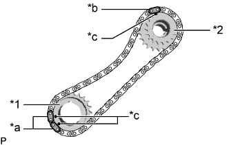
Align the 2 mark plates (pink) of the No. 1 chain sub-assembly with the 2 timing marks of the crankshaft timing sprocket and install the No. 1 chain sub-assembly to the crankshaft timing sprocket as shown in the illustration.
Table 21. Text in Illustration *1 Crankshaft Timing Sprocket *2 Injection Pump Drive Gear *a Mark Plate (Pink) *b Mark Plate (Yellow) *c Timing Mark -
Align the mark plate (yellow) of the No. 1 chain sub-assembly with the timing mark of the injection pump drive gear and install the No. 1 chain sub-assembly to the injection pump drive gear as shown in the illustration.
-
Install the crankshaft timing sprocket, injection pump drive gear and No. 1 chain sub-assembly to the crankshaft and supply pump shaft together.
-
- Click here
TIGHTEN NO. 1 CHAIN VIBRATION DAMPER
-
Tighten the No. 1 chain vibration damper to the cylinder block sub-assembly with the bolt.
21 N*m 214 kgf*cm 15 ft.*lbf
-
- Click here
INSTALL NO. 1 CHAIN TENSIONER ASSEMBLY
Note:
-
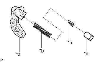
When the pin is removed from the No. 1 chain tensioner assembly, the plunger and spring may come off of the No. 1 chain tensioner assembly body, but this is not a malfunction.
-
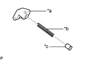
Before installing the plunger and spring to the No. 1 chain tensioner assembly body, check that they are free of foreign matter and not damaged.
Table 22. Text in Illustration *a No. 1 Chain Tensioner Assembly Body *b Spring *c Plunger
-
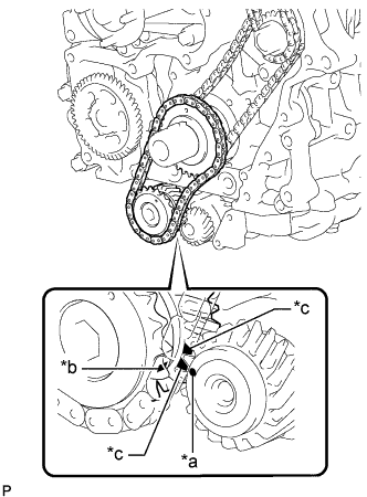
Install a new gasket and No. 1 chain tensioner assembly to the cylinder block sub-assembly with the 2 bolts.
10 N*m 102 kgf*cm 7 ft.*lbf Table 23. Text in Illustration *a Claw (Lower Side) *b Groove Tip:Align the claw (lower side) of the gasket with the groove of the No. 1 chain tensioner assembly body to install the No. 1 chain tensioner assembly as shown in the illustration.
-
- Click here
INSTALL SUPPLY PUMP SHAFT NUT
-
Temporarily install the crankshaft pulley and crankshaft pulley set bolt to the crankshaft.
-
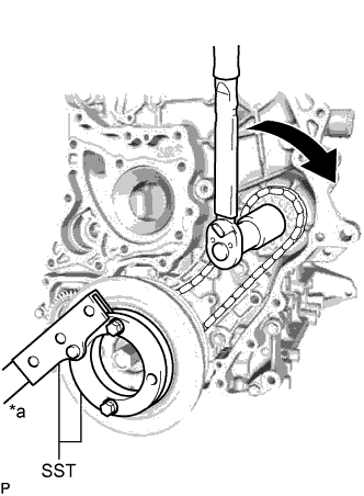
Using SST, hold the crankshaft pulley and install the supply pump shaft nut to the supply pump shaft.
09213-58014 91551-80840 09330-00021 137 N*m 1397 kgf*cm 101 ft.*lbf Table 24. Text in Illustration *a Hold Turn Note:If the supply pump shaft nut is tightened with torque higher than the specified torque, the No. 1 chain sub-assembly may break.
-
Remove the crankshaft pulley set bolt and crankshaft pulley from the crankshaft.
-
Make sure that the timing marks of the crankshaft timing sprocket and injection pump drive gear are aligned with the mark plates of the No. 1 chain sub-assembly as shown in the illustration.
Table 25. Text in Illustration *1 Crankshaft Timing Sprocket *2 Injection Pump Drive Gear *a Mark Plate (Pink) *b Mark Plate (Yellow) *c Timing Mark -
Remove the pin from the No. 1 chain tensioner assembly.
-
- Click here
INSTALL CAMSHAFT TIMING SPROCKET
-
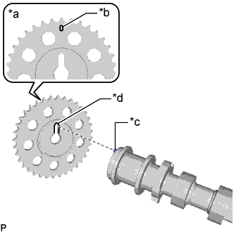
Temporarily install the 2 camshaft timing sprockets to the camshaft and No. 2 camshaft with the 2 camshaft timing sprocket bolts.
Table 26. Text in Illustration *a Engine Front Side *b Timing Mark *c Knock Pin *d Cutout Note:Make sure that the timing mark of the camshaft timing sprocket faces the front side of the engine.
Tip:Align the knock pins of the camshaft and No. 2 camshaft with the cutout of the camshaft timing sprocket to install the camshaft timing sprocket.
-
for Intake Side:
-
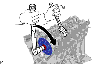
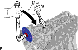
Using a wrench to hold the hexagonal portion of the camshaft, install the camshaft timing sprocket bolt to the camshaft.
81 N*m 826 kgf*cm 60 ft.*lbf Table 27. Text in Illustration *a Hold Turn Note:Be careful not to damage the camshaft or cylinder head sub-assembly with the wrench.
-
-
for Exhaust Side:
-
Using a wrench to hold the hexagonal portion of the No. 2 camshaft, install the camshaft timing sprocket bolt to the No. 2 camshaft.
81 N*m 826 kgf*cm 60 ft.*lbf Table 28. Text in Illustration *a Hold Turn Note:Be careful not to damage the No. 2 camshaft or cylinder head sub-assembly with the wrench.
-
-
- Click here
INSTALL NO. 2 CHAIN VIBRATION DAMPER
-
Install the No. 2 chain vibration damper to the timing chain case assembly with the 2 bolts.
21 N*m 214 kgf*cm 15 ft.*lbf
-
- Click here
INSTALL NO. 2 CHAIN SUB-ASSEMBLY
-
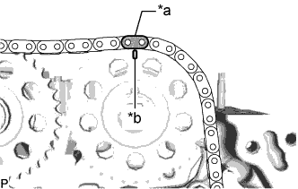
Align the mark plate (orange) of the No. 2 chain sub-assembly with the timing mark of the camshaft timing sprocket (intake side) and install the No. 2 chain sub-assembly to the camshaft timing sprocket (intake side) as shown in the illustration.
Table 29. Text in Illustration *a Mark Plate (Orange) *b Timing Mark -
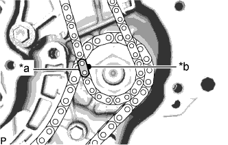
Align the mark plate (yellow) of the No. 2 chain sub-assembly with the timing mark of the injection pump drive gear and install the No. 2 chain sub-assembly to the injection pump drive gear as shown in the illustration.
Table 30. Text in Illustration *a Mark Plate (Yellow) *b Timing Mark -
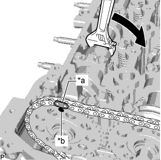
Using a wrench, turn the hexagonal portion of the No. 2 camshaft clockwise and align the mark plate (orange) of the No. 2 chain sub-assembly with the timing mark of the camshaft timing sprocket (exhaust side) to install the No. 2 chain sub-assembly to the camshaft timing sprocket (exhaust side).
Table 31. Text in Illustration *a Mark Plate (Orange) *b Timing Mark Turn
-
- Click here
INSTALL NO. 2 CHAIN TENSIONER SLIPPER
-
Install the No. 2 chain tensioner slipper to the timing chain case assembly with the bolt.
21 N*m 214 kgf*cm 15 ft.*lbf
-
- Click here
INSTALL NO. 2 CHAIN TENSIONER ASSEMBLY
-
Install the No. 2 chain tensioner assembly to the timing chain case assembly with the 2 bolts.
10 N*m 102 kgf*cm 7 ft.*lbf -
Remove the pin from the No. 2 chain tensioner assembly.
-
- Click here
INSTALL TIMING CHAIN GUIDE
-
Install the timing chain guide to the cylinder head sub-assembly with the bolt.
10 N*m 102 kgf*cm 7 ft.*lbf
-
- Click here
CHECK NO. 1 CYLINDER TO TDC/COMPRESSION
-
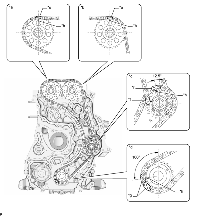
Make sure that the timing marks of the camshaft timing sprocket (exhaust side), camshaft timing sprocket (intake side), injection pump drive gear and crankshaft timing sprocket are at the positions shown in the illustration.
Table 32. Text in Illustration *a Camshaft Timing Sprocket (Exhaust Side) *b Camshaft Timing Sprocket (Intake Side) *c Injection Pump Drive Gear *d Crankshaft Timing Sprocket *e Mark Plate (Orange) *f Mark Plate (Yellow) *g Mark Plate (Pink) *h Timing Mark
-
- Click here
INSTALL ENGINE BALANCER ASSEMBLY
-
Set the engine balancer assembly to the cylinder block sub-assembly.
-
Install the engine balancer assembly to the cylinder block sub-assembly with the 8 bolts and tighten the bolts in the sequence shown in the illustration.
for bolt A 21 N*m 214 kgf*cm 15 ft.*lbf for bolt B 43 N*m 438 kgf*cm 32 ft.*lbf Bolt Length Item Specified Condition Bolt A 50 mm (1.97 in.) Bolt B 55 mm (2.17 in.) Table 33. Text in Illustration *a Bolt Type *b Tightening Order
-
- Click here
INSTALL BALANCE SHAFT TIMING SPROCKET, BALANCE SHAFT GEAR SUB-ASSEMBLY WITH NO. 3 CHAIN SUB-ASSEMBLY
Tip: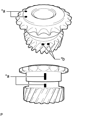
Before installing the balance shaft gear sub-assembly, make sure to confirm the positions of the timing marks and paint marks (pink).
Table 34. Text in Illustration *a Timing Mark *b Paint Mark (Pink)
-
Align the mark plate (yellow) of the No. 3 chain sub-assembly with the timing mark of the balance shaft timing sprocket and install the No. 3 chain sub-assembly to the balance shaft timing sprocket as shown in the illustration.
Table 35. Text in Illustration *1 Balance Shaft Timing Sprocket *2 Balance Shaft Gear Sub-assembly *a Mark Plate (Yellow) *b Timing Mark Note:Make sure that the timing plate of the No. 3 chain sub-assembly faces the front side of the engine.
-
Align the 2 mark plates (yellow) of the No. 3 chain sub-assembly with the 2 timing marks of the balance shaft timing gear sub-assembly and install the No. 3 chain sub-assembly to the balance shaft timing gear sub-assembly as shown in the illustration.
-
Apply engine oil to the position shown in the illustration.
-
Align the timing mark of the engine balancer assembly with the 2 paint marks (pink) and timing mark of the balance shaft gear sub-assembly, and then install the balance shaft timing sprocket, balance shaft gear sub-assembly with No. 3 chain sub-assembly to the crankshaft and engine balancer assembly as shown in the illustration.
Table 36. Text in Illustration *a Timing Mark (Engine Balancer Assembly Side) *b Timing Mark (Balance Shaft Gear Sub-assembly Side) *c Paint Mark (Pink)
(Balance Shaft Gear Sub-assembly Side)
-
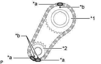
Make sure that the timing marks of the balance shaft timing sprocket and balance shaft gear sub-assembly are aligned with the mark plates of the No. 3 chain sub-assembly as shown in the illustration.
Table 37. Text in Illustration *1 Balance Shaft Timing Sprocket *2 Balance Shaft Gear Sub-assembly *a Mark Plate (Yellow) *b Timing Mark
-
- Click here
INSTALL NO. 1 BALANCE SHAFT THRUST PLATE
-
Apply engine oil to the front and rear surfaces of the No. 1 balance shaft thrust plate.
-
Install the No. 1 balance shaft thrust plate to the crankshaft with the bolt.
21 N*m 214 kgf*cm 15 ft.*lbf
-
- Click here
INSTALL NO. 3 CHAIN TENSIONER ASSEMBLY
Note:
-
When the pin is removed from the No. 3 chain tensioner assembly, the plunger and 2 springs may come off of the No. 3 chain tensioner assembly body, but this is not a malfunction.
-
Before installing the plunger and 2 springs to the No. 3 chain tensioner assembly body, check that they are free of foreign matter and not damaged.
Table 38. Text in Illustration *a No. 3 Chain Tensioner Assembly Body *b Spring *c Plunger
-
Install the No. 3 chain tensioner assembly to the engine balancer assembly with the 2 bolts.
10 N*m 102 kgf*cm 7 ft.*lbf -
Remove the pin from the No. 3 chain tensioner assembly.
-
- Click here
INSTALL OIL PUMP DRIVE GEAR
-
Install the oil pump drive gear to the crankshaft.
-
- Click here
INSTALL OIL PUMP RELIEF VALVE PLUG
-
Install a new gasket and oil pump relief valve plug to the timing chain cover sub-assembly.
46 N*m 469 kgf*cm 34 ft.*lbf
-
- Click here
INSTALL TIMING CHAIN COVER PLATE
-
Install the timing chain cover plate and new gasket with the 3 bolts.
10 N*m 102 kgf*cm 7 ft.*lbf
-
- Click here
INSTALL TIMING CHAIN COVER SUB-ASSEMBLY
-
Install the timing chain case gasket to the timing chain case assembly.
-
Clean and degrease the contact surfaces of the timing chain cover sub-assembly and timing chain case assembly.
-
Apply a coating of seal packing to the timing chain cover sub-assembly at the points shown in the illustration.
Table 39. Text in Illustration *a 2.0 to 3.0 mm (0.0787 to 0.118 in.) *b 2.5 to 3.5 mm (0.0984 to 0.138 in.) Seal packing Toyota Genuine Seal Packing Black, Three Bond 1207B or equivalent. Standard seal packing diameter 2.5 to 3.5 mm (0.0984 to 0.138 in.) Note:
-
Using non-residue solvent, clean and remove any oil from the installation surface.
-
Install the part within 3 minutes and tighten the bolts within 10 minutes after applying seal packing.
-
Do not add engine oil for at least 2 hours after installation.
-
Do not start the engine within 2 hours after installation.
-
-
Temporarily install the timing chain cover sub-assembly with the 20 bolts.
Table 40. Text in Illustration *a Type of bolt *b Tightening Bolt Length Item Length Thread Diameter Bolt A 40 mm (1.57 in.) 8.0 mm (0.315 in.) Bolt B 25 mm (0.984 in.) 8.0 mm (0.315 in.) -
Tighten the 20 bolts in the order shown in the illustration.
21 N*m 214 kgf*cm 15 ft.*lbf Note:Check the torque of bolt 1 after tightening bolt 20.
-
- Click here
INSTALL FRONT CRANKSHAFT OIL SEAL
-
Apply MP grease to the lip of a new crankshaft oil seal.
Note:
-
Keep the lip free of foreign objects.
-
Do not allow MP grease to contact the dust seal.
-
-
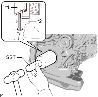
Using SST and a hammer, tap in the front crankshaft oil seal.
09214-76011 Table 41. Text in Illustration *1 Front Crankshaft Oil Seal *2 Timing Chain Cover Assembly *a 0 to 1.5 mm (0 to 0.0591 in.) Note:
-
The acceptable depth from the top of the timing chain cover assembly is 0 to 1.5 mm (0 to 0.0591 in.)
-
Keep the lip free from foreign matter.
-
Do not tap the front crankshaft oil seal at an angle.
-
Make sure that the front crankshaft oil seal is properly installed.
-
-
- Click here
INSTALL REAR ENGINE OIL SEAL RETAINER
-
Clean and degrease the contact surfaces of the rear engine oil seal retainer and cylinder block sub-assembly.
-
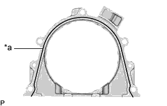
Apply seal packing to the rear engine oil seal retainer in the areas indicated in the illustration.
Seal packing Toyota Genuine Seal Packing Black, Three Bond 1207B or equivalent Standard seal diameter 3.0 to 4.0 mm (0.118 to 0.157 in.) Table 42. Text in Illustration *a Seal Packing Note:
-
Remove any engine oil from the contact surface.
-
Install the rear engine oil seal retainer within 3 minutes and tighten the bolts within 10 minutes after applying seal packing.
-
Do not add engine oil within 2 hours of installation.
-
Do not start the engine for at least 2 hours after the installation.
-
-
Install the rear engine oil seal retainer to the cylinder block sub-assembly, and then install the 5 bolts.
10 N*m 102 kgf*cm 7 ft.*lbf
-
- Click here
INSTALL REAR ENGINE OIL SEAL
-
Apply MP grease to the lip of a new rear engine oil seal.
Note:
-
Keep the lip free of foreign matter.
-
Do not allow MP grease to contact the dust seal.
-
-
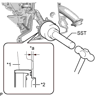
Using SST and a hammer, tap in the rear engine oil seal to the rear engine oil seal retainer edge.
09351-40010 09351-04010 09351-04020 Table 43. Text in Illustration *1 Rear Oil Seal Retainer *2 Rear Engine Oil Seal *a 0 to 1.0 mm (0 to 0.0394 in.) Note:
-
The acceptable depth from the top of the rear engine oil seal retainer is 0 to 1.0 mm (0 to 0.0394 in.)
-
Keep the lip free from foreign matter.
-
Do not tap the rear engine oil seal at an angle.
-
Make sure that the rear engine oil seal is properly installed.
-
-
- Click here
INSTALL OIL STRAINER SUB-ASSEMBLY
-
Install a new gasket and oil strainer sub-assembly to the cylinder block sub-assembly with the 5 bolts in several steps in the sequence shown in the illustration.
12 N*m 122 kgf*cm 9 ft.*lbf Tip:Make sure that the claw of the gasket faces the oil strainer sub-assembly.
-
- Click here
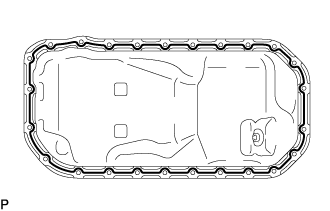
INSTALL OIL PAN SUB-ASSEMBLY
-
Clean and degrease the contact surfaces of the oil pan sub-assembly and cylinder block sub-assembly.
-
Apply seal packing in a continuous line as shown in the illustration.
Table 44. Text in Illustration 
Seal Packing Seal packing Toyota Genuine Seal Packing Black, Three Bond 1207B or equivalent Standard seal diameter 3.5 to 4.5 mm (0.138 to 0.177 in.) Note:
-
Remove any oil from the contact surface.
-
Install the oil pan sub-assembly within 3 minutes and tighten the bolts and nuts within 10 minutes after applying seal packing.
-
Do not add engine oil within 2 hours after installation.
-
Do not start the engine for at least 2 hours after installation.
-
-
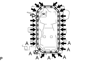
Install the oil pan sub-assembly to the cylinder block sub-assembly with the 23 bolts and 2 nuts.
10 N*m 102 kgf*cm 7 ft.*lbf Note:Check the torque of all nuts and bolts labeled A again.
-
- Click here
INSTALL ENGINE OIL LEVEL SENSOR
-
Install the engine oil level sensor to the oil pan sub-assembly with the 4 bolts.
12 N*m 122 kgf*cm 9 ft.*lbf -
Connect the engine oil level sensor connector.
-
- Click here
INSTALL CRANKSHAFT POSITION SENSOR
-
Apply a light coat of engine oil to the O-ring of the crankshaft position sensor.
-
Install the crankshaft position sensor with the bolt to the rear oil seal retainer.
10 N*m 102 kgf*cm 7 ft.*lbf Note:
-
When reusing the crankshaft position sensor, check the O-ring.
-
Make sure that the O-ring is not cracked or jammed when installing to the rear oil seal retainer.
-
Replace with a new part if it is dropped or if it receives a strong impact.
-
-
- Click here
INSTALL CRANKSHAFT POSITION SENSOR HARNESS BRACKET
-
Install the crankshaft position sensor harness bracket to the cylinder block sub-assembly with the bolt.
10 N*m 102 kgf*cm 7 ft.*lbf -
Connect the crankshaft position sensor connector.
-
- Click here
INSTALL NO. 1 CYLINDER BLOCK INSULATOR
-
Install the No. 1 cylinder block insulator to the cylinder block sub-assembly.
-
- Click here
INSTALL NO. 5 CYLINDER BLOCK INSULATOR
-
Install the No. 5 cylinder block insulator to the cylinder block sub-assembly.
-
- Click here
INSTALL CYLINDER HEAD COVER SUB-ASSEMBLY
-
Apply a light coat of engine oil to the O-ring of the camshaft position sensor.
-
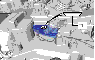
Install a new cylinder head cover gasket, No. 2 cylinder head cover gasket and 2 camshaft bearing cap oil hole gaskets to the cylinder head cover sub-assembly.
-
Clean and degrease the contact surfaces of the cylinder head cover sub-assembly and cylinder head sub-assembly.
-
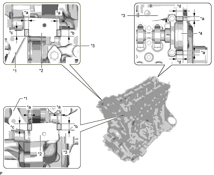
Apply seal packing as shown in the illustration.
Table 45. Text in Illustration *1 Timing Chain Cover Sub-assembly *2 Timing Chain Case Assembly *3 Cylinder Head Sub-assembly *4 No. 3 Camshaft Bearing Cap *a Seal Diameter: 3.0 to 6.0 mm (0.118 to 0.236 in.) *b Application Width: 7.0 mm (0.276 in.) *c Application Width: 9.0 mm (0.354 in.) *d Application Width: 11.0 mm (0.433 in.) Seal packing Toyota Genuine Seal Packing Black, Three Bond 1207B or equivalent Standard seal diameter 3.0 to 6.0 mm (0.118 to 0.236 in.) Note:
-
Remove any oil from the contact surface.
-
Install the cylinder head cover sub-assembly within 3 minutes and tighten the bolts within 10 minutes after applying seal packing.
-
Do not add engine oil for at least 2 hours after installation.
-
Do not start the engine within 2 hours after installation.
-
-
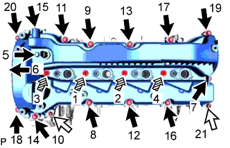
Tighten the 14 bolts, 4 nozzle holder clamp seats, 2 nuts and camshaft position sensor in the order shown in the illustration.
10 N*m 107 kgf*cm 7 ft.*lbf Note:
-
When reusing the camshaft position sensor, check the O-rings.
-
Make sure that the O-ring is not cracked or jammed when installing it on the cylinder head cover sub-assembly.
-
Replace with a new part if it is dropped or if it receives a strong impact.
-
Check the torque of bolts 1 to 4 again.
Table 46. Text in Illustration Bolt Nut 
Nozzle Holder Clamp Seat -
-
- Click here
INSTALL OIL FILLER CAP GASKET
-
Install the oil filler cap gasket to the oil filler cap sub-assembly.
-
- Click here
INSTALL OIL FILLER CAP SUB-ASSEMBLY
-
Install the oil filler cap sub-assembly to the cylinder head cover sub-assembly.
-
- Click here
INSTALL NOZZLE HOLDER GASKET
-
Install 4 new nozzle holder gaskets to the cylinder head cover sub-assembly.
-
- Click here
TEMPORARILY INSTALL INJECTOR ASSEMBLY
Tip:Before installing the injector assembly, check for carbon, foreign matter, etc. on the seal surfaces of the cylinder head sub-assembly and injector assembly. If there is foreign matter, remove it before installing the injector assembly.
-
Install 4 new injection nozzle seats to the cylinder head sub-assembly.
-
Apply a light coat of engine oil to the O-ring on each injector assembly.
-
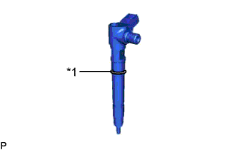
Install a new O-ring to each injector assembly.
Table 47. Text in Illustration *1 O-Ring -
Install the 4 injector assemblies to the cylinder head sub-assembly.
Note:Fit the injector assembly to the injection nozzle seats.
-
Install the nozzle holder clamps and washers as shown in the illustration.
Table 48. Text in Illustration *1 Washer Note:Pay attention to the mounting orientation (beveled edge) of the washer.
-
Temporarily install the nozzle holder clamp bolts.
Note:When temporarily installing the nozzle holder clamp bolt to the No. 1 nozzle holder clamp, make sure that the bolt and clamp are not at an angle.
Tip:Apply a light coat of engine oil to the threads of the nozzle holder clamp bolts.
-
- Click here
INSTALL OIL FILTER BRACKET
-
Install 2 new O-rings to the cylinder block sub-assembly.
-
Install the oil filter bracket to the cylinder block sub-assembly with the 2 nuts and bolt.
21 N*m 214 kgf*cm 15 ft.*lbf
-
- Click here
INSTALL OIL FILTER UNION
-
Using a 27 mm deep socket wrench, install the oil filter union to the oil filter bracket.
29 N*m 300 kgf*cm 22 ft.*lbf
-
- Click here
INSTALL OIL FILTER SUB-ASSEMBLY
-
Check and clean the oil filter sub-assembly installation surface.
-
Apply clean engine oil to the gasket of a new oil filter sub-assembly.
-
Lightly screw the oil filter sub-assembly into place by hand. Tighten it until the gasket contacts the seat.
-
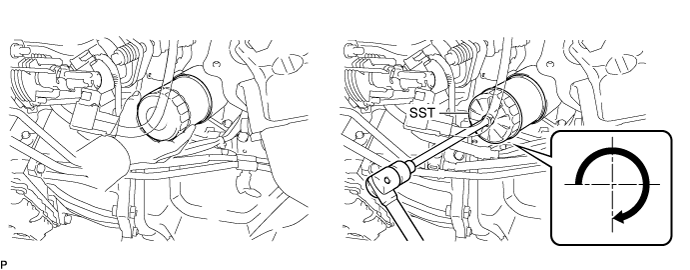
Using SST, tighten the oil filter sub-assembly.
09228-07502 Table 49. Text in Illustration 3/4 Turn - - -
Depending on the space available, choose from the following.
If enough space is available, use a torque wrench to tighten the oil filter sub-assembly.
12 N*m 122 kgf*cm 9 ft.*lbf -
If enough space is not available to use a torque wrench, tighten the oil filter sub-assembly 3/4 of a turn by hand or with a common wrench.
-
- Click here
INSTALL ENGINE OIL COOLER SET
-
Apply a light coat of engine oil to the 2 new O-rings.
-
Install the 2 O-rings to the cylinder block sub-assembly.
-
Install a new water outlet pipe gasket to the cylinder block sub-assembly.
-
Install the engine oil cooler set to the cylinder block sub-assembly with the bolt and 5 nuts.
15 N*m 153 kgf*cm 11 ft.*lbf
-
- Click here
INSTALL FRONT NO. 1 ENGINE MOUNTING BRACKET RH
-
Install the front No. 1 engine mounting bracket RH to the cylinder block sub-assembly with the 4 bolts.
68 N*m 693 kgf*cm 50 ft.*lbf
-
- Click here
INSTALL GENERATOR BRACKET SUB-ASSEMBLY
-
Install the generator bracket sub-assembly to the cylinder head sub-assembly and timing chain case assembly with the 4 bolts.
21 N*m 214 kgf*cm 15 ft.*lbf
-
- Click here
INSTALL NO. 3 CYLINDER BLOCK INSULATOR
-
Install the No. 3 cylinder block insulator to the cylinder block sub-assembly.
-
- Click here
INSTALL FRONT NO. 1 ENGINE MOUNTING BRACKET LH
-
Install the front No. 1 engine mounting bracket LH to the cylinder block sub-assembly with the 4 bolts.
68 N*m 693 kgf*cm 50 ft.*lbf
-
- Click here
INSTALL NO. 2 CYLINDER BLOCK INSULATOR
-
Install the No. 2 cylinder block insulator to the front No. 1 engine mounting bracket LH.
-
- Click here
INSTALL NO. 1 ENGINE HANGER
-
Install the No. 1 engine hanger to the cylinder head sub-assembly with the 2 bolts.
26 N*m 265 kgf*cm 19 ft.*lbf
-