БЛОК ДВИГАТЕЛЯ ПРОВЕРКА

-
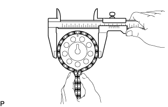
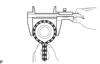
INSPECT NO. 1 CHAIN SUB-ASSEMBLY
-
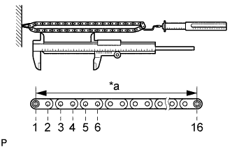
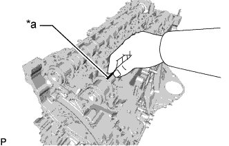
Text in Illustration *a Measuring Point Using a spring scale, pull the No. 1 chain sub-assembly with a force of 147 N (15 kgf, 33.0 lbf) as shown in the illustration.
-
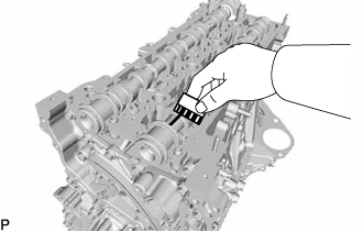
Using a vernier caliper, measure the length of 16 pins.
Maximum chain elongation 144.7 mm (5.70 in.) Tech Tips
Perform the measurement at 3 random places.
If the elongation is more than the maximum, replace the No. 1 chain sub-assembly.
-
-
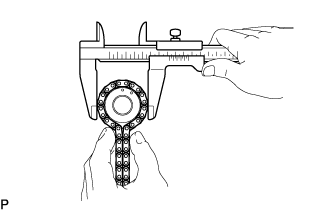
INSPECT NO. 2 CHAIN SUB-ASSEMBLY
-
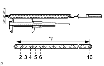
Text in Illustration *a Measuring Point Using a spring scale, pull the No. 2 chain sub-assembly with a force of 147 N (15 kgf, 33.0 lbf) as shown in the illustration.
-
Using a vernier caliper, measure the length of 16 pins.
Maximum chain elongation 121.6 mm (4.79 in.) Tech Tips
Perform the measurement at 3 random places.
If the elongation is more than the maximum, replace the No. 2 chain sub-assembly.
-
-
INSPECT NO. 3 CHAIN SUB-ASSEMBLY
-
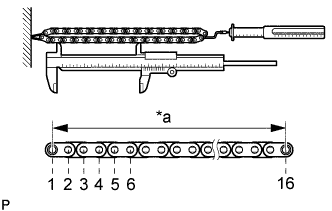
Text in Illustration *a Measuring Point Using a spring scale, pull the No. 3 chain sub-assembly with a force of 147 N (15 kgf, 33.0 lbf) as shown in the illustration.
-
Using a vernier caliper, measure the length of 16 pins.
Maximum chain elongation 121.6 mm (4.79 in.) Tech Tips
Perform the measurement at 3 random places.
If the elongation is more than the maximum, replace the No. 3 chain sub-assembly.
-
-
INSPECT NO. 1 CHAIN TENSIONER ASSEMBLY
Note
-
When the pin is removed from the No. 1 chain tensioner assembly, the plunger and spring may come off of the No. 1 chain tensioner assembly body, but this is not a malfunction.
-
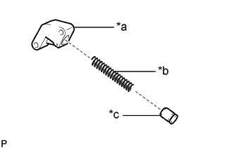
Before installing the plunger and spring to the No. 1 chain tensioner assembly body, check that they are free of foreign matter and not damaged.
Text in Illustration *a No. 1 Chain Tensioner Assembly Body *b Spring *c Plunger
-
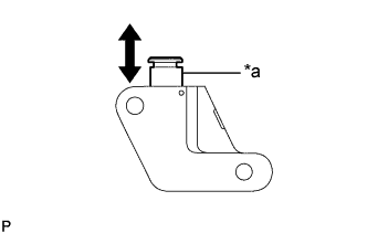
Text in Illustration *a Plunger Push the plunger and check that it moves smoothly.
If necessary, replace the No. 1 chain tensioner assembly.
-
-
INSPECT NO. 2 CHAIN TENSIONER ASSEMBLY
-
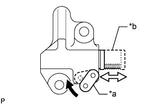
Text in Illustration *a Stopper Plate *b Plunger Move the stopper plate upward to release the lock. Push the plunger and check that it moves smoothly.
If necessary, replace the No. 2 chain tensioner assembly.
-
-
INSPECT NO. 3 CHAIN TENSIONER ASSEMBLY
Note
-
When the pin is removed from the No. 3 chain tensioner assembly, the plunger and 2 springs may come off of the No. 3 chain tensioner assembly body, but this is not a malfunction.
-
Before installing the plunger and 2 springs to the No. 3 chain tensioner assembly body, check that they are free of foreign matter and not damaged.
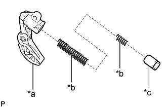
Text in Illustration *a No. 3 Chain Tensioner Assembly Body *b Spring *c Plunger
-
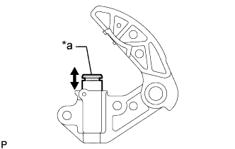
Text in Illustration *a Plunger Push the plunger and check that it moves smoothly.
If necessary, replace the No. 3 chain tensioner assembly.
-
-
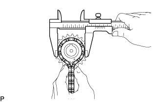
INSPECT CAMSHAFT TIMING SPROCKET
-
Wrap the No. 2 chain sub-assembly around the camshaft timing sprocket.
-
Using a vernier caliper, measure the camshaft timing sprocket diameter with the No. 2 chain sub-assembly.
Minimum sprocket with chain diameter 97.79 mm (3.85 in.) If the diameter is less than the minimum, replace the No. 2 chain sub-assembly and camshaft timing sprocket.
Tech Tips
The vernier caliper must contact the No. 2 chain sub-assembly rollers for the measurement.
-
-
INSPECT CRANKSHAFT TIMING SPROCKET
-
Wrap the No. 1 chain sub-assembly around the crankshaft timing sprocket.
-
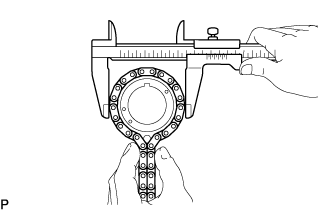
Using a vernier caliper, measure the crankshaft timing sprocket diameter with the No. 1 chain sub-assembly.
Minimum sprocket with chain diameter 71.26 mm (2.81 in.) If the diameter is less than the minimum, replace the No. 1 chain sub-assembly and crankshaft timing sprocket.
Tech Tips
The vernier caliper must contact the No. 1 chain sub-assembly rollers for the measurement.
-
-
INSPECT INJECTION PUMP DRIVE GEAR
-
for No. 1 Chain Sub-assembly Side:
-
Wrap the No. 1 chain sub-assembly around the injection pump drive gear.
-
Using a vernier caliper, measure the injection pump drive gear diameter with the No. 1 chain sub-assembly.
Minimum gear with chain diameter 71.26 mm (2.81 in.) If the diameter is less than the minimum, replace the No. 1 chain sub-assembly and injection pump drive gear.
Tech Tips
The vernier caliper must contact the No. 1 chain sub-assembly rollers for the measurement.
-
-
for No. 2 Chain Sub-assembly Side:
-
Wrap the No. 2 chain sub-assembly around the injection pump drive gear.
-
Using a vernier caliper, measure the injection pump drive gear diameter with the No. 2 chain sub-assembly.
Minimum gear with chain diameter 52.32 mm (2.06 in.) If the diameter is less than the minimum, replace the No. 2 chain sub-assembly and injection pump drive gear.
Tech Tips
The vernier caliper must contact the No. 2 chain sub-assembly rollers for the measurement.
-
-
-
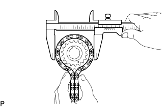
INSPECT BALANCE SHAFT TIMING SPROCKET
-
Wrap the No. 3 chain sub-assembly around the balance shaft timing sprocket.
-
Using a vernier caliper, measure the balance shaft timing sprocket diameter with the No. 3 chain sub-assembly.
Minimum sprocket with chain diameter 86.72 mm (3.41 in.) If the diameter is less than the minimum, replace the No. 3 chain sub-assembly and balance shaft timing sprocket.
Tech Tips
The vernier caliper must contact the No. 3 chain sub-assembly rollers for the measurement.
-
-
INSPECT BALANCE SHAFT GEAR SUB-ASSEMBLY
-
Wrap the No. 3 chain sub-assembly around the balance shaft gear sub-assembly.
-
Using a vernier caliper, measure the balance shaft gear sub-assembly diameter with the No. 3 chain sub-assembly.
Minimum sprocket with chain diameter 57.34 mm (2.26 in.) If the diameter is less than the minimum, replace the No. 3 chain sub-assembly and balance shaft gear sub-assembly.
Tech Tips
The vernier caliper must contact the No. 3 chain sub-assembly rollers for the measurement.
-
-
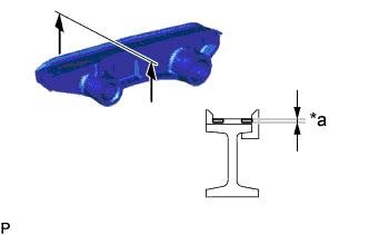
INSPECT NO. 1 CHAIN TENSIONER SLIPPER
-
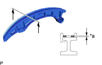
Text in Illustration *a Depth Measure the depth of wear of the No. 1 chain tensioner slipper.
Maximum depth 1.0 mm (0.0394 in.) If the depth is more than the maximum, replace the No. 1 chain tensioner slipper.
-
-
INSPECT NO. 2 CHAIN TENSIONER SLIPPER
-
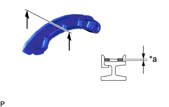
Text in Illustration *a Depth Measure the depth of wear of the No. 2 chain tensioner slipper.
Maximum depth 1.0 mm (0.0394 in.) If the depth is more than the maximum, replace the No. 2 chain tensioner slipper.
-
-
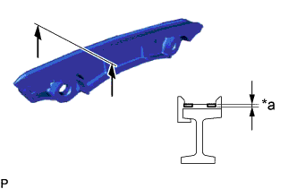
INSPECT NO. 1 CHAIN VIBRATION DAMPER
-
Text in Illustration *a Depth Measure the depth of wear of the No. 1 chain vibration damper.
Maximum depth 1.0 mm (0.0394 in.) If the depth is more than the maximum, replace the No. 1 chain vibration damper.
-
-
INSPECT NO. 2 CHAIN VIBRATION DAMPER
-
Text in Illustration *a Depth Measure the depth of wear of the No. 2 chain vibration damper.
Maximum depth 1.0 mm (0.0394 in.) If the depth is more than the maximum, replace the No. 2 chain vibration damper.
-
-
INSPECT TIMING CHAIN GUIDE
-
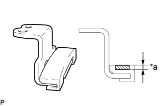
Text in Illustration *a Depth Measure the depth of wear of the timing chain guide.
Maximum depth 1.0 mm (0.0394 in.) If the depth is more than the maximum, replace the timing chain guide.
-
-
INSPECT INTAKE MANIFOLD
-
Using a precision straightedge and feeler gauge, measure the warpage of the surface where the intake manifold contacts the cylinder head sub-assembly.
Maximum warpage 0.10 mm (0.00394 in.) If the warpage is more than the maximum, replace the intake manifold.
-
-
INSPECT EXHAUST MANIFOLD
-
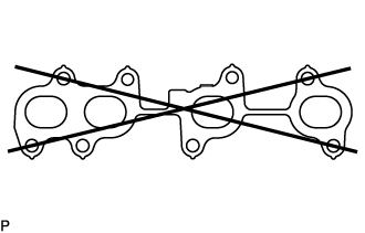
Using a precision straightedge and feeler gauge, measure the warpage of the surface where the exhaust manifold contacts the cylinder head sub-assembly.
Maximum warpage 0.10 mm (0.00394 in.) If the warpage is more than the maximum, replace the exhaust manifold.
-
-
INSPECT CAMSHAFT
-
Inspect the camshaft runout.
-
Place the camshaft on V-blocks.
-
Using a dial indicator, measure the circle runout at the center journal.
Maximum circle runout 0.03 mm (0.00118 in.) If the circle runout is more than the maximum, replace the camshaft.
Tech Tips
Check the oil clearance after replacing the camshaft.
-
-
Inspect the cam lobes.
-
Using a micrometer, measure the cam lobe height.
Standard cam lobe height 41.425 to 41.525 mm (1.631 to 1.635 in.) Minimum cam lobe height 41.375 mm (1.629 in.) If the cam lobe height is less than the minimum, replace the camshaft.
-
-
Inspect the camshaft journals.
-
Using a micrometer, measure the journal diameter.
Standard Journal Diameter Item Specified Condition No. 1 journal 34.449 to 34.465 mm (1.356 to 1.357 in.) Other journals 22.990 to 23.007 mm (0.905 to 0.906 in.) If the journal diameter is not as specified, check the oil clearance.
-
-
-
INSPECT NO. 2 CAMSHAFT
-
Inspect the No. 2 camshaft runout.
-
Place the No. 2 camshaft on V-blocks.
-
Using a dial indicator, measure the circle runout at the center journal.
Maximum circle runout 0.03 mm (0.00118 in.) If the circle runout is more than the maximum, replace the No. 2 camshaft.
Tech Tips
Check the oil clearance after replacing the No. 2 camshaft.
-
-
Inspect the cam lobes.
-
Using a micrometer, measure the cam lobe height.
Standard cam lobe height 41.694 to 41.794 mm (1.641 to 1.645 in.) Minimum cam lobe height 41.644 mm (1.640 in.) If the cam lobe height is less than the minimum, replace the No. 2 camshaft.
-
-
Inspect the No. 2 camshaft journals.
-
Using a micrometer, measure the journal diameter.
Standard Journal Diameter Item Specified Condition No. 1 journal 34.449 to 34.465 mm (1.356 to 1.357 in.) Other journals 22.990 to 23.007 mm (0.905 to 0.906 in.) If the journal diameter is not as specified, check the oil clearance.
-
-
-
INSPECT CAMSHAFT OIL CLEARANCE
-
Clean the No. 1 camshaft bearing cap, No. 2 camshaft bearing caps, camshaft journals and No. 2 camshaft journals.
-
Place the camshaft and No. 2 camshaft on the cylinder head sub-assembly.
-
Text in Illustration *a Plastigage Lay a strip of Plastigage across each of the camshaft journals.
-
Install the No. 1 camshaft bearing cap and No. 2 camshaft bearing caps to the cylinder head sub-assembly Click here.
Note
Do not turn the camshaft and No. 2 camshaft.
-
Remove the No. 1 camshaft bearing cap and No. 2 camshaft bearing caps from the cylinder head sub-assembly Click here.
-
Measure the Plastigage at its widest point.
Standard Oil Clearance Item Specified Condition No. 1 journal 0.040 to 0.077 mm (0.00157 to 0.00303 in.) Other journals 0.025 to 0.062 mm (0.000984 to 0.00244 in.) Maximum Oil Clearance Item Specified Condition No. 1 journal 0.117 mm (0.00461 in.) Other journals 0.102 mm (0.00402 in.) If the camshaft oil clearance is more than the maximum, replace the camshaft. If necessary, replace the cylinder head sub-assembly.
-
Completely remove the Plastigage from the camshaft journals.
-
-
INSPECT CYLINDER HEAD SET BOLT
-
w/ Washer:
-
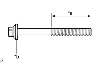
Text in Illustration *a Measuring Area *b Washer Using a vernier caliper, measure the thread outside diameter of the cylinder head set bolt.
Minimum diameter 11.4 mm (0.449 in.) If the diameter is less than the minimum, replace the cylinder head set bolt.
-
-
w/o Washer:
-
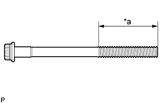
Text in Illustration *a Measuring Area Using a vernier caliper, measure the thread outside diameter of the cylinder head set bolt.
Minimum diameter 12.8 mm (0.504 in.) If the diameter is less than the minimum, replace the cylinder head set bolt and cylinder head set bolt spacer.
-
-
-
INSPECT NO. 1 VALVE ROCKER ARM SUB-ASSEMBLY
-
Turn the roller by hand and check that it turns smoothly.
If the roller does not turn smoothly, replace the No. 1 valve rocker arm sub-assembly.
-
-
INSPECT VALVE LASH ADJUSTER ASSEMBLY
Note
-
Keep the adjuster free from dirt and foreign matter.
-
Use only clean engine oil.
-
Place the valve lash adjuster assembly into a container full of new engine oil.
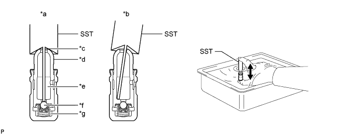
Text in Illustration *a CORRECT *b INCORRECT *c Taper Part *d Plunger *e Low Pressure Chamber *f Check Ball *g High Pressure Chamber - - -
Insert the tip of SST into the plunger and use the tip to press down on the check ball inside the plunger.
- SST
- 09276-75010
-
Squeeze SST and the valve lash adjuster assembly together to move the plunger up and down 5 to 6 times.
-
Check the movement of the plunger and bleed air.
OK Plunger moves up and down. Note
When bleeding high-pressure air from the compression chamber, make sure that the tip of SST is actually pressing the check ball as shown in the illustration. If the check ball is not pressed, air will not bleed.
-
After bleeding the air, remove SST. Then try to quickly and firmly press the plunger with your fingers.
OK Plunger is very difficult to move. If the result is not as specified, replace the valve lash adjuster assembly.
-
-
INSPECT ENGINE BALANCER ASSEMBLY
-
Inspect the balance shaft thrust clearance.
-
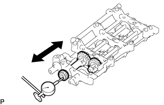
Using a dial indicator, measure the thrust clearance while moving the No. 1 balance shaft back and forth.
Standard thrust clearance 0.05 to 0.09 mm (0.00197 to 0.00354 in.) Maximum thrust clearance 0.09 mm (0.00354 in.) If the thrust clearance is more than the maximum, replace the engine balancer assembly.
-
-
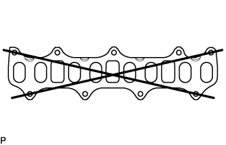
Inspect the balance shaft thrust backlash.
-
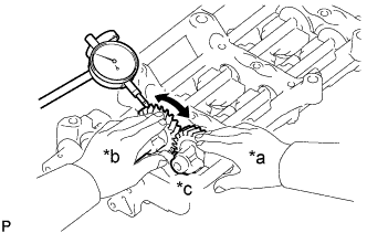
Text in Illustration *a No. 2 Balance Shaft Side *b No. 1 Balance Shaft Side *c Fix Fix the No. 2 balance shaft in place, and then, using a dial indicator, measure the backlash of the No. 1 and No. 2 balance shafts as shown in the illustration.
Standard backlash 0.01 to 0.12 mm (0.000394 to 0.00472 in.) Maximum backlash 0.12 mm (0.00472 in.) If the backlash is more than the maximum, replace the engine balancer assembly.
-
-