РАСПРЕДВАЛ УСТАНОВКА

Note
-
When replacing the parts in the following chart (A), replace the No. 1 injection pipe sub-assembly, No. 2 injection pipe sub-assembly and/or fuel inlet pipe sub-assembly with new ones.
Replaced Parts (A) Pipes Requiring New Replacement Injector assembly (including shuffling the injector assemblies between the cylinders)
-
No. 1 injection pipe sub-assembly
-
No. 1 injection pipe sub-assembly
Supply pump assembly Fuel inlet pipe sub-assembly
-
Supply pump assembly
-
Common rail assembly
-
Cylinder block sub-assembly
-
Cylinder head sub-assembly
-
Cylinder head gasket
-
Timing chain case assembly
-
No. 1 injection pipe sub-assembly
-
No. 2 injection pipe sub-assembly
-
Fuel inlet pipe sub-assembly
-
-
After removing the No. 1 injection pipe sub-assembly, No. 2 injection pipe sub-assembly and/or fuel inlet pipe sub-assembly, clean them with a brush and compressed air.
-
The injector assembly is a precision instrument. Do not use the injector assembly if it is struck or dropped.
-
The supply pump assembly is a precision instrument. Do not use the supply pump assembly if it is struck or dropped.
-
Hold the supply pump assembly itself during removal and installation. Do not hold the pre-stroke control valve or fuel pipe, etc.
-
Make sure foreign matter does not enter the fuel path.
-
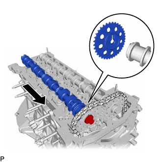
INSTALL CAMSHAFT
-
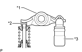
Text in Illustration *1 Valve Rocker Arm Sub-assembly *2 Valve Stem Cap *3 Valve Lash Adjuster Assembly Check that the valve rocker arm sub-assembly is firmly set to the valve lash adjuster assembly.
-
Apply a light coat of engine oil to the camshaft journals of the cylinder head sub-assembly and the thrust portion of the camshaft.
-
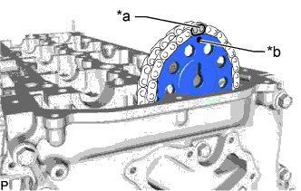
Text in Illustration *a Paint Mark *b Timing Mark Align the paint mark of the No. 2 chain sub-assembly and timing mark of the camshaft timing sprocket, and install the camshaft timing sprocket to the No. 2 chain sub-assembly.
Tech Tips
Make sure the timing mark of the camshaft timing sprocket face the front side.
-
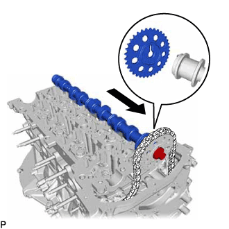
Align the knock pin of the No. 1 camshaft to the groove of the sprocket and install the No. 1 camshaft to the camshaft timing sprocket, and set the bolt.
-
Text in Illustration *a Paint Mark *b Timing Mark Align the paint mark of the No. 2 chain sub-assembly and timing mark of the camshaft timing sprocket, and install the camshaft timing sprocket to the No. 2 chain sub-assembly.
Tech Tips
Make sure the timing mark of the camshaft timing sprocket face the front side.
-
Align the knock pin of the No. 2 camshaft to the groove of the sprocket and install the No. 2 camshaft to the camshaft timing sprocket, and set the bolt.
Tech Tips
Groove is at the rear end of the No. 2 camshaft.
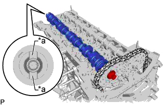
Text in Illustration *a Groove -
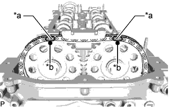
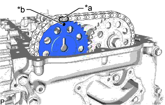
Text in Illustration *a Paint Mark *b Timing Mark Check the timing mark of the camshaft timing sprocket and the paint mark of the No. 2 chain sub-assembly.
-
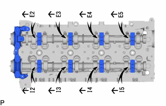
Set the No. 1 camshaft bearing cap and 8 No. 2 camshaft bearing caps to the cylinder head sub-assembly as shown in the illustration.
-
Temporarily install the 20 bolts.
-
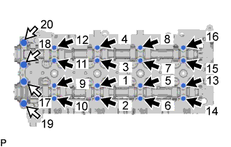
Uniformly tighten the 20 bolts in several steps in the order shown in the illustration.
- Torque:
- for bolt A
- 10 N*m { 102 kgf*cm, 7 ft.*lbf }
- for bolt B
- 21 N*m { 214 kgf*cm, 15 ft.*lbf }
Text in Illustration 
Bolt A 
Bolt B -
Text in Illustration *1 No. 1 Camshaft *2 No. 2 Camshaft Hold the hexagonal portion of the No. 1 camshaft and No. 2 camshaft with a wrench, and tighten the 2 bolts.
- Torque:
- 81 N*m { 826 kgf*cm, 60 ft.*lbf }
Note
Be careful not to damage the cylinder head sub-assembly with the wrench.
-
Remove the pin from the No. 2 chain tensioner assembly.
-
Install a new gasket and the oil pump relief valve plug to the timing chain cover.
- Torque:
- 46 N*m { 469 kgf*cm, 34 ft.*lbf }
-
Clean and degrease the contact surfaces of the cylinder head sub-assembly and No. 3 camshaft bearing cap.
-
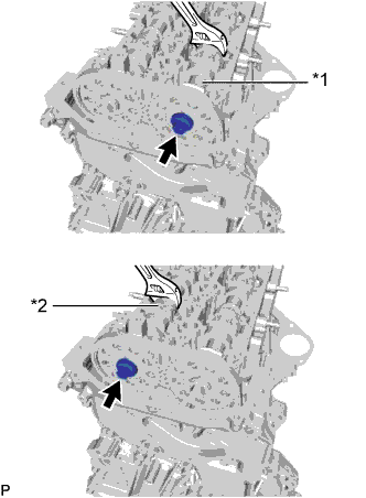
Text in Illustration *a Engine Front *b Seal Packing Apply seal packing to the specified areas as shown in the illustration.
Seal packing Toyota Genuine Seal Packing Black, Three Bond 1207B or equivalent Standard seal diameter 3.0 mm (0.118 in.) Note
-
Do not allow seal packing to contact the oil passage of the No. 3 camshaft bearing cap.
-
After applying seal packing, install the No. 3 camshaft bearing cap within 3 minutes and tighten the bolts within 10 minutes.
-
Do not start the engine for at least 2 hours after installation.
-
-
Install the No. 3 camshaft bearing cap with the 2 bolts.
- Torque:
- 21 N*m { 214 kgf*cm, 15 ft.*lbf }
-
Wipe off excess seal packing from between No. 3 camshaft bearing cap and cylinder head sub-assembly.
-
-
INSTALL TIMING CHAIN GUIDE
-
Install the timing chain guide to the cylinder head sub-assembly with the bolt.
- Torque:
- 10 N*m { 102 kgf*cm, 7 ft.*lbf }
-
-
INSTALL CYLINDER HEAD COVER SUB-ASSEMBLY
-
Apply a light coat of engine oil to the O-ring of the camshaft position sensor.
-
Install a new cylinder head cover gasket, No. 2 cylinder head cover gasket and 2 camshaft bearing cap oil hole gaskets to the cylinder head cover sub-assembly.
-
Clean and degrease the contact surfaces of the cylinder head cover sub-assembly and cylinder head sub-assembly.
-
Apply seal packing as shown in the illustration.
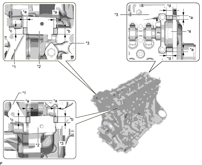
Text in Illustration *1 Timing Chain Cover Sub-assembly *2 Timing Chain Case Assembly *3 Cylinder Head Sub-assembly *4 No. 3 Camshaft Bearing Cap *a Seal Diameter: 3.0 to 6.0 mm (0.118 to 0.236 in.) *b Application Width: 7.0 mm (0.276 in.) *c Application Width: 9.0 mm (0.354 in.) *d Application Width: 11.0 mm (0.433 in.) Seal packing Toyota Genuine Seal Packing Black, Three Bond 1207B or equivalent Standard seal diameter 3.0 to 6.0 mm (0.118 to 0.236 in.) Note
-
Remove any oil from the contact surface.
-
Install the cylinder head cover sub-assembly within 3 minutes and tighten the bolts within 10 minutes after applying seal packing.
-
Do not add engine oil for at least 2 hours after installation.
-
Do not start the engine within 2 hours after installation.
-
-
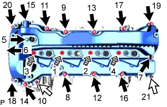
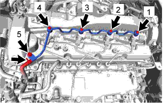
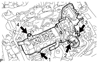
Tighten the 14 bolts, 4 nozzle holder clamp seats, 2 nuts and camshaft position sensor in the order shown in the illustration.
- Torque:
- 10 N*m { 107 kgf*cm, 7 ft.*lbf }
Note
-
When reusing the camshaft position sensor, check the O-rings.
-
Make sure that the O-ring is not cracked or jammed when installing it on the cylinder head cover sub-assembly.
-
Replace with a new part if it is dropped or if it receives a strong impact.
-
Check the torque of bolts 1 to 4 again.
Text in Illustration Bolt Nut 
Nozzle Holder Clamp Seat
-
-
INSTALL CAMSHAFT OIL SEAL RETAINER
Note
If the camshaft oil seal retainer is dropped, replace it with a new one.
-
Before installing a new camshaft oil seal retainer, clean the installation surface of the No. 3 camshaft bearing cap and cylinder head sub-assembly and remove any foreign matter.
-
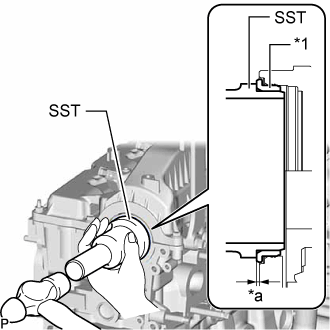
Text in Illustration *1 Camshaft Oil Seal Retainer *a Depth Using SST and a hammer, tap in a new camshaft oil seal retainer to the No. 3 camshaft bearing cap and cylinder head sub-assembly as shown in the illustration.
- SST
- 09223-22010
Standard depth -0.5 to 0.8 mm (-0.0197 to 0.0315 in.)
-
-
INSTALL VACUUM PUMP ASSEMBLY
-
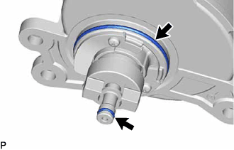
Coat 2 new O-rings with engine oil, and install them to the vacuum pump assembly.
-
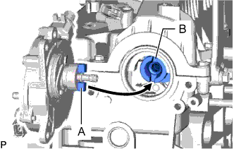
Install the vacuum pump assembly so that the coupling teeth of the vacuum pump assembly labeled A and the groove of the No. 2 camshaft labeled B can engage.
-
Install the vacuum pump assembly to the cylinder head sub-assembly with the 3 bolts.
- Torque:
- 21 N*m { 214 kgf*cm, 15 ft.*lbf }
-
Connect the No. 1 vacuum transmitting hose sub-assembly to the vacuum pump assembly.
-
-
CONNECT BRACKET
-
Connect the bracket to the cylinder head sub-assembly with the 2 bolts.
- Torque:
- 10 N*m { 102 kgf*cm, 7 ft.*lbf }
-
Attach the 2 clamp and connect the 2 connectors to the bracket.
-
-
INSTALL NOZZLE HOLDER GASKET
-
Install 4 new nozzle holder gaskets to the cylinder head cover sub-assembly.
-
-
TEMPORARILY INSTALL INJECTOR ASSEMBLY
Tech Tips
Before installing the injector assembly, check for carbon, foreign matter, etc. on the seal surfaces of the cylinder head sub-assembly and injector assembly. If there is foreign matter, remove it before installing the injector assembly.
-
Install 4 new injection nozzle seats to the cylinder head sub-assembly.
-
Apply a light coat of engine oil to the O-ring on each injector assembly.
-
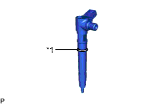
Text in Illustration *1 O-Ring Install a new O-ring to each injector assembly.
-
Install the 4 injector assemblies to the cylinder head sub-assembly.
Note
Fit the injector assembly to the injection nozzle seats.
-
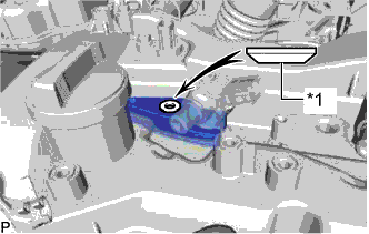
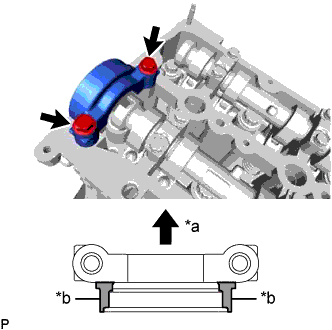
Text in Illustration *1 Washer Install the nozzle holder clamps and washers as shown in the illustration.
Note
Pay attention to the mounting orientation (beveled edge) of the washer.
-
Temporarily install the nozzle holder clamp bolts.
Note
When temporarily installing the nozzle holder clamp bolt to the No. 1 nozzle holder clamp, make sure that the bolt and clamp are not at an angle.
Tech Tips
Apply a light coat of engine oil to the threads of the nozzle holder clamp bolts.
-
-
TEMPORARILY INSTALL NO. 1 INJECTION PIPE SUB-ASSEMBLY AND NO. 2 INJECTION PIPE SUB-ASSEMBLY
-
Temporarily install the 2 No. 2 injection pipe sub-assemblies with the 4 union nuts.
-
Temporarily install the 2 No. 1 injection pipe sub-assemblies with the 4 union nuts.
-
-
TIGHTEN INJECTOR ASSEMBLY
-
Tighten the 4 nozzle holder clamp bolts.
- Torque:
- 21 N*m { 214 kgf*cm, 15 ft.*lbf }
-
-
TIGHTEN NO. 1 INJECTION PIPE SUB-ASSEMBLY AND NO. 2 INJECTION PIPE SUB-ASSEMBLY
-
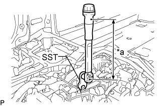
Text in Illustration *a Torque Wrench Fulcrum Length Using SST, tighten the 8 union nuts of the No. 1 and No. 2 injection pipe sub-assemblies.
- Torque:
- Specified tightening torque
- 40 N*m { 408 kgf*cm, 30 ft.*lbf }
Tech Tips
-
Calculate the torque wrench reading when changing the fulcrum length of the torque wrench.
-
When using SST (fulcrum length of 50 mm (1.97 in.)) + torque wrench (fulcrum length of 180 mm (7.09 in.)): 31 N*m (316 kgf*cm, 23 ft.*lbf)
-
-
INSTALL NOZZLE LEAKAGE PIPE ASSEMBLY
-
Temporarily install the nozzle leakage pipe assembly and 4 new gaskets with the 4 union bolts and bolt.
-
Tighten the 4 union bolts and bolt in the order shown in the illustration.
- Torque:
- 10 N*m { 102 kgf*cm, 7 ft.*lbf }
-
Connect the No. 5 fuel hose to the nozzle leakage pipe assembly.
-
-
INSTALL NO. 1 FUEL PIPE
-
Connect the No. 1 fuel pipe to the No. 4 fuel pipe.
-
Install a new gasket and the No. 1 fuel pipe to the cylinder head cover sub-assembly and No. 1 injector holder with the union bolt and bolt.
- Torque:
- for bolt
- 10 N*m { 102 kgf*cm, 7 ft.*lbf }
- for union bolt
- 36 N*m { 367 kgf*cm, 27 ft.*lbf }
-
-
INSTALL HARNESS BRACKET
-
Install the harness bracket with the bolt.
- Torque:
- 10 N*m { 102 kgf*cm, 7 ft.*lbf }
-
-
INSTALL WIRING HARNESS CLAMP BRACKET
-
Install the wiring harness clamp bracket the cylinder head cover sub-assembly with the bolt.
- Torque:
- 10 N*m { 102 kgf*cm, 7 ft.*lbf }
-
Connect the pressure discharge valve connector to the common rail assembly.
-
-
INSTALL INSTALL NO. 1 EGR COOLER AND NO. 2 EGR VALVE ASSEMBLY WITH ELECTRIC EGR CONTROL VALVE ASSEMBLY
-
Temporarily install the No. 1 EGR cooler and No. 2 EGR valve assembly with electric EGR control valve assembly to the intake manifold with the 4 bolts.
-
Tighten the 4 bolts in the order shown in the illustration.
Tech Tips
Make sure to tighten the bolts in the order.
- Torque:
- 21 N*m { 214 kgf*cm, 15 ft.*lbf }
-
-
INSTALL VACUUM CONTROL VALVE SET
-
Install the vacuum control valve set to the intake manifold with the 2 bolts.
- Torque:
- 10 N*m { 102 kgf*cm, 7 ft.*lbf }
-
Connect the 2 vacuum hoses to the vacuum control valve set and No. 2 EGR valve assembly.
-
Connect the connector to the vacuum control valve set.
-
-
INSTALL NO. 1 EGR PIPE SUB-ASSEMBLY
-
Using an E8 "TORX" socket wrench, install 2 new stud bolts to the exhaust manifold.
- Torque:
- 10 N*m { 102 kgf*cm, 7 ft.*lbf }
-
Install 2 new gaskets and the No. 1 EGR pipe sub-assembly to the exhaust manifold and EGR valve adapter with 4 new nuts.
- Torque:
- 29 N*m { 296 kgf*cm, 21 ft.*lbf }
-
Connect the No. 1 EGR pipe sub-assembly to the vacuum transmitting pipe sub-assembly with the bolt.
- Torque:
- 10 N*m { 102 kgf*cm, 7 ft.*lbf }
-
-
INSTALL NO. 2 EGR PIPE
-
Install 2 new gaskets and No. 2 EGR pipe to the electric EGR control valve assembly and the intake manifold with the 4 nuts.
- Torque:
- 29 N*m { 296 kgf*cm, 21 ft.*lbf }
-
-
CONNECT NO. 4 WATER BY-PASS PIPE SUB-ASSEMBLY
-
Connect the No. 4 water by-pass pipe sub-assembly to the intake manifold with the 2 bolts.
- Torque:
- 10 N*m { 102 kgf*cm, 7 ft.*lbf }
-
Connect the water hose to the No. 2 EGR valve assembly, and slide the clamp to secure the hose.
-
Connect the No. 7 water by-pass hose to the No. 1 EGR cooler, and slide the clamp to secure the hose.
-
-
INSTALL NO. 3 WATER BY-PASS PIPE SUB-ASSEMBLY
-
Install the No. 3 water by-pass pipe sub-assembly to the No. 1 EGR cooler with the 2 bolts.
- Torque:
- 10 N*m { 102 kgf*cm, 7 ft.*lbf }
-
Connect the No. 9 water by-pass hose to the electric EGR control valve assembly, and slide the clamp to secure the hose.
-
Connect the No. 8 water by-pass hose to the No. 3 water by-pass pipe sub-assembly, and slide the clamp to secure the hose.
-
Connect the No. 4 fuel hose to the No. 3 water by-pass pipe sub-assembly.
-
-
INSTALL EGR VALVE BRACKET
-
Install the EGR valve bracket to the electric EGR control valve assembly and intake manifold with the bolt and nut.
- Torque:
- 21 N*m { 214 kgf*cm, 15 ft.*lbf }
-
-
INSTALL DIESEL THROTTLE BODY ASSEMBLY
-
Connect the connector to install the emission control valve wire to the diesel throttle body assembly.
-
Install a new gasket and the diesel throttle body assembly with the 2 bolts and 2 nuts.
- Torque:
- 10 N*m { 102 kgf*cm, 7 ft.*lbf }
-
Connect the connector and clamp.
-
-
INSTALL GAS FILTER BRACKET
-
Install the gas filter bracket to the diesel throttle body assembly with the bolt.
- Torque:
- 10 N*m { 102 kgf*cm, 7 ft.*lbf }
-
-
INSTALL GAS FILTER
-
Install the gas filter to the gas filter bracket.
-
Connect the 2 vacuum hoses to the turbo pressure sensor and intake manifold.
-
-
INSTALL TURBO PRESSURE SENSOR
-
Install the diesel turbo pressure sensor to the No. 3 water by-pass pipe sub-assembly with the bolt.
- Torque:
- 10 N*m { 102 kgf*cm, 7 ft.*lbf }
-
Connect the connector to the diesel turbo pressure sensor.
-
-
INSTALL NO. 2 WATER BY-PASS PIPE
-
Connect the heater hose to the No. 2 water by-pass pipe.
-
Install the No. 2 water by-pass pipe with the 2 bolts.
- Torque:
- 10 N*m { 102 kgf*cm, 7 ft.*lbf }
-
-
INSTALL NO. 16 WATER BY-PASS HOSE
-
Install the No. 16 water by-pass hose to the No. 1 EGR cooler and No. 2 water by-pass pipe, and slide the 2 clamps to secure the hoses.
-
-
INSTALL VACUUM TUBE CONNECTOR HOSE
-
Install the vacuum tube connector hose to the cylinder head sub-assembly and intake manifold with the 2 bolts.
- Torque:
- 10 N*m { 102 kgf*cm, 7 ft.*lbf }
-
Connect the vacuum tube connector hose to the vacuum pump assembly, and slide the clamp to secure the hose.
-
-
INSTALL ENGINE ASSEMBLY