-
When replacing the parts in the following chart (A), replace the No. 1 injection pipe sub-assembly, No. 2 injection pipe sub-assembly and/or fuel inlet pipe sub-assembly with new ones.
Replaced Parts (A) Pipes Requiring New Replacement Injector assembly (including shuffling the injector assemblies between the cylinders)
-
No. 1 injection pipe sub-assembly
-
No. 1 injection pipe sub-assembly
Supply pump assembly Fuel inlet pipe sub-assembly
-
Supply pump assembly
-
Common rail assembly
-
Cylinder block sub-assembly
-
Cylinder head sub-assembly
-
Cylinder head gasket
-
Timing chain case assembly
-
No. 1 injection pipe sub-assembly
-
No. 2 injection pipe sub-assembly
-
Fuel inlet pipe sub-assembly
-
-
After removing the No. 1 injection pipe sub-assembly, No. 2 injection pipe sub-assembly and/or fuel inlet pipe sub-assembly, clean them with a brush and compressed air.
-
The injector assembly is a precision instrument. Do not use the injector assembly if it is struck or dropped.
-
The supply pump assembly is a precision instrument. Do not use the supply pump assembly if it is struck or dropped.
-
Hold the supply pump assembly itself during removal and installation. Do not hold the pre-stroke control valve or fuel pipe, etc.
-
Make sure foreign matter does not enter the fuel path.
- Click here
REMOVE CAMSHAFT
- Click here
REMOVE TIMING CHAIN COVER ASSEMBLY
- Click here
REMOVE NO. 1 VALVE ROCKER ARM SUB-ASSEMBLY
-
Remove the 16 No. 1 valve rocker arm sub-assemblies from the 16 valve lash adjuster assemblies.
-
- Click here
REMOVE VALVE LASH ADJUSTER ASSEMBLY
-
Remove the 16 valve lash adjuster assemblies from the cylinder head sub-assembly.
-
- Click here
REMOVE CYLINDER HEAD SUB-ASSEMBLY
-
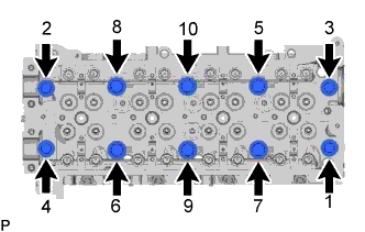
Uniformly loosen the 10 cylinder head set bolts in several passes in the sequence shown in the illustration. Then remove the 10 cylinder head set bolts and 6 cylinder head set bolt spacers.
Note:
-
Cylinder head sub-assembly warpage or cracking could result from removing bolts in the incorrect order.
-
Be careful not to drop the cylinder head set bolt spacers into the cylinder head sub-assembly.
-
-
Lift the cylinder head sub-assembly from the ring pins on the cylinder block sub-assembly, and place the cylinder head sub-assembly on wooden blocks on a bench.
Note:Be careful not to damage the contact surfaces of the cylinder head sub-assembly and cylinder block sub-assembly.
Tip:If the cylinder head sub-assembly is difficult to remove, use a screwdriver to pry between the cylinder head sub-assembly and cylinder block sub-assembly.
-
- Click here
REMOVE CYLINDER HEAD GASKET
-
Remove the cylinder head gasket from the cylinder block sub-assembly.
-
- Click here
INSPECT CYLINDER HEAD SET BOLT
-
w/ Washer:
-
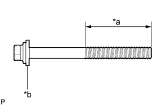
Using a vernier caliper, measure the thread outside diameter of the cylinder head set bolt.
Minimum diameter 11.4 mm (0.449 in.) Table 1. Text in Illustration *a Measuring Area *b Washer If the diameter is less than the minimum, replace the cylinder head set bolt.
-
-
w/o Washer:
-
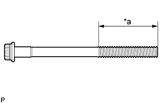
Using a vernier caliper, measure the thread outside diameter of the cylinder head set bolt.
Minimum diameter 12.8 mm (0.504 in.) Table 2. Text in Illustration *a Measuring Area If the diameter is less than the minimum, replace the cylinder head set bolt and cylinder head set bolt spacer.
-
-