| DTC Code | DTC Name |
|---|---|
| ECM Power Source Circuit |
DESCRIPTION
When the ignition switch is turned to ON, the battery voltage is applied to terminal IGSW of the ECM. The MREL output signal from ECM causes a current to flow to the coil, closing the contacts of the EFI MAIN relay and supplying power to terminal +B of the ECM.
INSPECTION PROCEDURE
-
After replacing the ECM, the new ECM needs registration (Click here) and initialization (Click here).
-
Inspect the fuses of circuits related to this system before performing the following inspection procedure.
PROCEDURE
- Click here
CHECK HARNESS AND CONNECTOR (ECM - BODY GROUND)
-
Disconnect the ECM connector.
-
Measure the resistance according to the value(s) in the table below.
Standard Resistance: Tester Connection Condition Specified Condition D105-109 (E1) - Body ground Always Below 1 Ω
- OKClick here
- NGClick here
-
- Click here
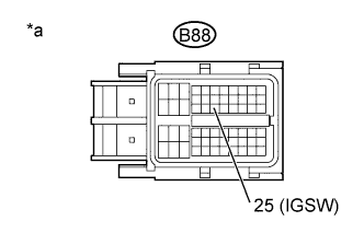
CHECK TERMINAL VOLTAGE (IGSW TERMINAL VOLTAGE)
-
Disconnect the ECM connector.
-
Turn the ignition switch to ON.
-
Measure the voltage according to the value(s) in the table below.
Standard Voltage Tester Connection Condition Specified Condition B88-25 (IGSW) - Body ground Ignition switch ON 11 to 14 V Table 1. Text in Illustration *a Front view of wire harness connector
(to ECM)
- OKClick here
- NGClick here
-
- Click here
INSPECT NO. 1 INTEGRATION RELAY (EFI MAIN RELAY)
-
Inspect the No. 1 integration relay (EFI MAIN relay) (Click here).
- OKClick here
- NGClick here
-
- Click here
CHECK HARNESS AND CONNECTOR (EFI MAIN RELAY - ECM, EFI MAIN RELAY - BODY GROUND)
-
Check the harness and connector between the No. 1 integration relay (EFI MAIN relay) and ECM.
-
Remove the No. 1 integration relay from the No. 1 engine room relay block and junction block assembly.
-
Disconnect the ECM connector.
-
Measure the resistance according to the value(s) in the table below.
Standard Resistance Tester Connection Condition Specified Condition 10B-4 - B88-1 (+B) Always Below 1 Ω 10B-2 - B88-28 (MREL) Always Below 1 Ω 10B-4 or B88-1 (+B) - Body ground Always 10 kΩ or higher 10B-2 or B88-28 (MREL) - Body ground Always 10 kΩ or higher -
Reconnect the ECM connector.
-
Reinstall the No. 1 integration relay.
-
-
Check the harness and connector between the No. 1 integration relay (EFI MAIN relay) and body ground.
-
Remove the No. 1 integration relay from the No. 1 engine room relay block and junction block assembly.
-
Measure the resistance according to the value(s) in the table below.
Standard Resistance Tester Connection Condition Specified Condition 10B-3 - Body ground Always Below 1 Ω -
Reinstall the No. 1 integration relay.
-
- OKClick here
- NGClick here
-
- Click here
INSPECT IGNITION SWITCH
-
Inspect the ignition switch (Click here).
- OKClick here
- NGClick here
-
- Click here
REPAIR OR REPLACE HARNESS OR CONNECTOR
- Click here
REPLACE INTEGRATION NO. 1 RELAY (EFI MAIN RELAY)
- Click here
REPAIR OR REPLACE HARNESS OR CONNECTOR (BATTERY - MAIN RELAY)
- Click here
REPLACE IGNITION SWITCHClick here
- Click here
REPAIR OR REPLACE HARNESS OR CONNECTOR (BATTERY - IGNITION SWITCH, IGNITION SWITCH - ECM)