СИСТЕМА ECD, Diagnostic DTC:P0489, P0490
| DTC Code | DTC Name |
|---|---|
| P0489 | Exhaust Gas Recirculation Control Circuit Low |
| P0490 | Exhaust Gas Recirculation Control Circuit High |
DESCRIPTION
The EGR system recirculates exhaust gases in a way that suits every driving condition. The recirculated gas mixes with intake air. Therefore, the EGR system can slow combustion speed and keep the combustion temperature down. This helps reduce NOx emission.
In order to increase EGR circulation efficiency, the ECM adjusts the lift amount of the EGR valve and the throttle valve angle.
| DTC Detection Drive Pattern | DTC Detection Condition | Trouble Area |
|---|---|---|
| 5 seconds after engine is started | Open or short in VRV for EGR circuit for 5 seconds or more (1 trip detection logic). |
|
| DTC Detection Drive Pattern | DTC Detection Condition | Trouble Area |
|---|---|---|
| 5 seconds after engine is started | Open or short in VRV for EGR circuit for 5 seconds or more (1 trip detection logic). |
|
| DTC No. | Data List |
|---|---|
| P0489 |
|
| P0490 |
WIRING DIAGRAM
Refer to DTC P0400 Click here.
INSPECTION PROCEDURE
Note
-
Inspect the fuses of circuits related to this system before performing the following inspection procedure.
-
After replacing the ECM, the new ECM needs registration Click here and initialization Click here.
Tech Tips
-
Read freeze frame data using the GTS. The ECM records vehicle and driving condition information as freeze frame data the moment a DTC is stored. When troubleshooting, freeze frame data can help determine if the vehicle was running or stopped, if the engine was warmed up or not, and other data from the time the malfunction occurred.
PROCEDURE
-
INSPECT VRV FOR EGR
-
Inspect the VRV for EGR Click here.
NG 
REPLACE ELECTRIC EGR CONTROL VALVE ASSEMBLY Click here
OK 
-
-
CHECK TERMINAL VOLTAGE (POWER SOURCE)
-
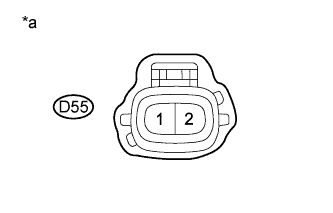
Text in Illustration *a Front view of wire harness connector
(to VRV for EGR)
Disconnect the VRV for EGR connector.
-
Measure the voltage according to the value(s) in the table below.
Standard Voltage Tester Connection Switch Condition Specified Condition D55-1 - Body ground Ignition switch ON 11 to 14 V -
Reconnect the VRV for EGR connector.
NG
REPAIR OR REPLACE HARNESS OR CONNECTOR Click here
OK
-
-
CHECK HARNESS AND CONNECTOR (VRV FOR EGR - ECM)
-
Disconnect the VRV for EGR connector.
-
Disconnect the ECM connector.
-
Measure the resistance according to the value(s) in the table below.
Standard Resistance Tester Connection Condition Specified Condition D55-2 - D105-83 (EGR) Always Below 1 Ω D55-2 or D105-83 (EGR) - Body ground Always 10 kΩ or higher -
Reconnect the VRV for EGR connector.
-
Reconnect the ECM connector.
NG
REPAIR OR REPLACE HARNESS OR CONNECTOR Click here
OK
-
-
REPLACE ECM
-
Replace the ECM Click here.
NEXT
CONFIRM WHETHER MALFUNCTION HAS BEEN SUCCESSFULLY REPAIRED Click here
-
-
REPLACE ELECTRIC EGR CONTROL VALVE ASSEMBLY
-
Replace the electric EGR control valve assembly Click here.
NEXT
CONFIRM WHETHER MALFUNCTION HAS BEEN SUCCESSFULLY REPAIRED Click here
-
-
REPAIR OR REPLACE HARNESS OR CONNECTOR
-
Repair or replace the harness or connector.
Tech Tips
If the voltage at the VRV for EGR connector is not 11 to 14 V, repair or replace the harness and connector between the VRV for EGR and the EFI MAIN relay.
NEXT
-
-
CONFIRM WHETHER MALFUNCTION HAS BEEN SUCCESSFULLY REPAIRED
-
Connect the GTS to the DLC3.
-
Clear the DTCs Click here.
-
Turn the ignition switch off for 30 seconds or more.
-
Start the engine.
-
Idle the engine for 5 seconds or more.
-
Enter the following menus: Powertrain / Engine and ECT / Trouble Codes.
-
Confirm that the DTC is not output again.
NEXT 
END
-