ДАТЧИК ПОЛОЖЕНИЯ КОЛЕНЧАТОГО ВАЛА УСТАНОВКА

-
INSTALL CRANKSHAFT POSITION SENSOR
-
Apply a light coat of engine oil to the O-ring of the crankshaft position sensor.
-
Install the crankshaft position sensor with the bolt to the rear oil seal retainer.
- Torque:
- 10 N*m { 102 kgf*cm, 7 ft.*lbf }
Note
-
When reusing the crankshaft position sensor, check the O-ring.
-
Make sure that the O-ring is not cracked or jammed when installing to the rear oil seal retainer.
-
Replace with a new part if it is dropped or if it receives a strong impact.
-
-
INSTALL CRANKSHAFT POSITION SENSOR HARNESS BRACKET
-
Install the crankshaft position sensor harness bracket with the bolt to the cylinder block sub-assembly.
- Torque:
- 10 N*m { 102 kgf*cm, 7 ft.*lbf }
-
-
INSTALL CONNECTING WIRE
-
Connect the 2 connectors and clamp and install the connecting wire.
-
-
INSTALL NO. 5 CYLINDER BLOCK INSULATOR
-
Install the No. 5 cylinder block insulator to the cylinder block sub-assembly.
-
-
INSTALL NO. 1 CYLINDER BLOCK INSULATOR
-
Install the No. 1 cylinder block insulator to the cylinder block sub-assembly.
-
-
INSTALL REAR END PLATE
-
Install the rear end plate to the cylinder block sub-assembly with the bolt.
- Torque:
- 10 N*m { 102 kgf*cm, 7 ft.*lbf }
-
-
INSTALL FLYWHEEL SUB-ASSEMBLY
-
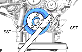
Using SST, hold the crankshaft pulley.
- SST
- 09213-58014 ( 91551-80840 )
- 09330-00021
-
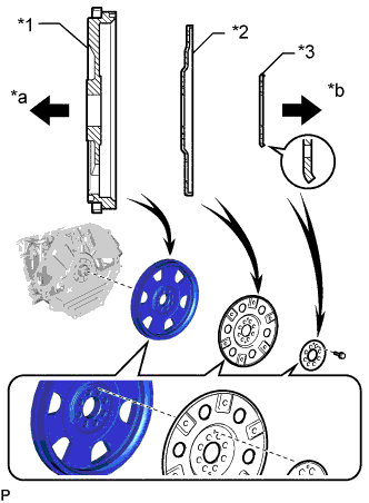
Text in Illustration *1 Flywheel Sub-assembly *2 Pump Impeller Drive Plate *3 Rear Drive Plate Spacer *a Engine Side *b Transmission Side Install the flywheel sub-assembly, the pump impeller drive plate and the rear drive plate spacer to the crankshaft with the 8 bolts.
Note
-
Align either hole in the pump impeller drive plate and either hole in the rear drive plate spacer with the knock pin of the flywheel sub-assembly, and then install the flywheel sub-assembly, the pump impeller drive plate and the rear drive plate spacer to the crankshaft.
-
Do not start the engine for at least 1 hour after installation.
Tech Tips
As the rear drive plate spacer and pump impeller drive plate are not reversible, be sure to install them in the direction shown in the illustration.
-
-

Install and uniformly tighten and tighten the 8 bolts in several steps in the sequence shown in the illustration.
- Torque:
- 178 N*m { 1815 kgf*cm, 131 ft.*lbf }
-
Install the crankshaft pulley cover to the crankshaft pulley with the 4 bolts.
- Torque:
- 21 N*m { 214 kgf*cm, 15 ft.*lbf }
-
-
INSTALL AUTOMATIC TRANSMISSION ASSEMBLY