СИСТЕМА ECD РЕЖИМЫ DATA LIST / ACTIVE TEST
-
DATA LIST
Tech Tips
Using the GTS to read the Data List allows the values or states of switches, sensors, actuators and other items to be read without removing any parts. This non-intrusive inspection can be very useful because intermittent conditions or signals may be discovered before parts or wiring is disturbed. Reading the Data List information early in troubleshooting is one way to save diagnostic time.
Note
In the table below, the values listed under "Normal Condition" are reference values. Do not depend solely on these reference values when deciding whether a part is faulty or not.
-
Warm up the engine.
-
Turn the ignition switch off.
-
Connect the GTS to the DLC3.
-
Turn the ignition switch to ON.
-
Start the engine.
-
Turn the GTS on.
-
Enter the following menus: Powertrain / Engine and ECT / Data List.
Tech Tips
-
To display the list box, press the pull down menu button next to "Primary". Then select a measurement group.
-
When you select a measurement group, the ECU data belonging to that group is displayed.
-
Measurement Group List / Description
-
All Data / All data
-
Primary / -
-
Engine Control / Engine control system related data
-
Common Rail / Fuel system related data
-
Common Rail (ALL) / Fuel system related detailed data
-
Diesel EGR / EGR system related data
-
Diesel Throttle / Diesel throttle system related data
-
VN Turbo / VN turbo related data
-
Diesel Exhaust / Exhaust system related data
-
Diesel Starting / "Difficult to start" related data
-
Diesel Rough Idle / "Rough idle" related data
-
Diesel Lack of Power / "Lack of power" related data
-
Diesel Knocking / "Knocking" related data
-
Diesel Black Smoke / "Black smoke" related data
-
Monitor Status / Monitor status related data
-
Charging Control / Charging control system related data
-
Compression / Data used during "Check the Cylinder Compression" Active Test
-
A/T / Automatic transaxle system related data
-
Vehicle Information / Vehicle information
-
Catalytic Converter / Catalytic Converter related data
-
-
Check the values by referring to the table below.
Note
Normal Condition: If no idling conditions are specified, the shift lever should be in N, and the A/C switch and all accessory switches should be off.
-
-
Engine Control
Calculate Load Tester Display Measurement Item/Range Normal Condition Type Cause of Out of Range Calculate Load Load calculated by ECM/
Min.: 0%, Max.: 100%
-
Idling: 6.6 to 14.2%
-
Running without load (3000 rpm): 15.5 to 24.0%
Calculated by ECM Malfunction in which turbo pressure or mass air flow decreases Diagnostic Note:
Calculated load = (Final injection volume / max. injection volume at current engine speed) x 100.
MAF Tester Display Measurement Item/Range Normal Condition Type Cause of Out of Range MAF Air flow rate from mass air flow meter/
Min.: 0 gm/sec, Max.: 400 gm/sec
Idling:
-
3.0 to 15.0 gm/sec (EGR on)
-
10.0 to 21.0 gm/sec (EGR off)
Running without load (3000 rpm):
-
45.0 to 89.0 gm/sec (EGR on)
-
72.0 to 94.0 gm/sec (EGR off)
Sensor output (mass air flow meter sub-assembly)
-
Mass air flow meter sub-assembly
-
Mass air flow meter sub-assembly circuit
-
Intake related clog or leak
-
Exhaust related clog
-
Turbocharger sub-assembly
-
Leak or clog in passages for turbocharger
-
Malfunction in which EGR valve does not close
Symptoms when out of range:
Rough idling
Diagnostic Note:
Based on the MAF, the ECM controls the fuel injection volume, injection timing, EGR, etc.
Engine Speed Tester Display Measurement Item/Range Normal Condition Type Cause of Out of Range Engine Speed Engine speed/
Min.: 0 rpm, Max.: 6000 rpm
-
50 to 400 rpm: Cranking
-
650 to 750 rpm: Idling with warm engine
Sensor output (crankshaft position sensor)
-
Crankshaft position sensor
-
Crankshaft position sensor circuit
Diagnostic Note:
When the crankshaft position sensor is malfunctioning, "Engine Speed" is approximately 0 or varies greatly from the actual engine speed.
Target Idle Engine Speed Tester Display Measurement Item/Range Normal Condition Type Cause of Out of Range Target Idle Engine Speed Target Idling Engine Speed/
Min.: 0 rpm, Max.: 10000 rpm
- Target idling speed (ECM calculated value) - MAP Tester Display Measurement Item/Range Normal Condition Type Cause of Out of Range MAP Absolute pressure inside intake manifold/
Min.: 0 kPa, Max.: 320 kPa
Idling:
-
96 to 105 kPa (EGR on)
-
97 to 107 kPa (EGR off)
Running without load (3000 rpm):
-
118 to 123 kPa (EGR on)
-
106 to 119 kPa (EGR off)
Sensor output (manifold absolute pressure sensor)
-
Manifold absolute pressure sensor
-
Intake related clog or leak
-
Exhaust related clog
-
Turbocharger sub-assembly
-
Leak or clog in passages for turbocharger
-
EGR valve stuck open
-
Exhaust leak
-
Throttle valve stuck closed
Symptoms when out of range:
Lack of power
Diagnostic Note:
-
When the ignition switch is ON or the vehicle is idling, the intake manifold absolute pressure and atmospheric pressure are approximately the same (standard atmospheric pressure = 101 kPa).
Above approximately 1500 rpm, the turbo becomes effective and the pressure becomes higher than atmospheric pressure.
-
Inspect while comparing with "Target Booster Pressure".
-
With the accelerator fully open, if the actual manifold absolute pressure (MAP) is low compared to the target booster pressure by at least 20 kPa for 5 seconds or more, a feeling of insufficient power will occur.
Vehicle Speed Tester Display Measurement Item/Range Normal Condition Type Cause of Out of Range Vehicle Speed Vehicle speed/
Min.: 0 km/h, Max.: 255 km/h
Actual vehicle speed Sensor output (speed sensor)
-
Speed sensor
-
Speed sensor circuit
Coolant Temp Tester Display Measurement Item/Range Normal Condition Type Cause of Out of Range Coolant Temp Engine coolant temperature/
Min.: -40°C, Max.: 140°C
After warming up engine: 70 to 90°C (158 to 194°F) Sensor output (engine coolant temperature sensor)
-
Engine coolant temperature sensor
-
Thermostat
Symptoms when out of range:
Difficulty starting when engine is cold, rough idle, black smoke, lack of power
Diagnostic Note:
-
If the value is -40°C (-40°F) or 140°C (284°F), the sensor circuit is open or shorted.
-
After a long soak, the coolant temperature, intake air temperature and ambient temperature are approximately equal.
Intake Air Tester Display Measurement Item/Range Normal Condition Type Cause of Out of Range Intake Air Intake air temperature/
Min.: -40°C, Max.: 140°C
Equivalent to temperature at location of mass air flow meter sub-assembly Sensor output (intake air temperature sensor (built into mass air flow meter sub-assembly)) Intake air temperature sensor Diagnostic Note:
-
After a long soak, the engine coolant temperature, intake air temperature and ambient temperature are approximately equal.
-
If the value is -40°C (-40°F) or 140°C (284°F), the sensor circuit is open or shorted.
Initial Engine Coolant Temp Tester Display Measurement Item/Range Normal Condition Type Cause of Out of Range Initial Engine Coolant Temp Initial engine coolant temperature/
Min.: -40°C, Max.: 120°C
Engine coolant temperature when engine started Sensor output when engine started - Diagnostic Note:
For freeze frame data, this tells whether the malfunction happened at a cold start or with a warm engine.
Initial Intake Air Temp Tester Display Measurement Item/Range Normal Condition Type Cause of Out of Range Initial Intake Air Temp Initial intake air temperature/
Min.: -40°C, Max.: 120°C
Intake air temperature when engine started Sensor output when engine started - Intake Air Temp (Turbo) Tester Display Measurement Item/Range Normal Condition Type Cause of Out of Range Intake Air Temp (Turbo) Intake air temperature after intercooler/
Min.: -40°C, Max.: 190°C
70°C (158°F) or less Sensor output (intake air temperature sensor after intercooler) Decreased cooling efficiency of intercooler (contamination, clogging) Diagnostic Note:
-
This is the intake air temperature at the intake manifold (after the intercooler).
-
During fail-safe operation, the value is set to 165°C (329°F). As the value is set to a high temperature, the manifold absolute pressure may be suppressed and there may be a lack of power.
Glow Relay Request Tester Display Measurement Item/Range Normal Condition Type Cause of Out of Range Glow Relay Request Status of the glow relay request/
ON or OFF
- - - Glow Control Unit Duty Tester Display Measurement Item/Range Normal Condition Type Cause of Out of Range Glow Control Unit Duty Glow control unit duty/
Min.: 0%, Max.: 127.5%
- Result of ECU calculations - Diagnostic Note:
This is the ECM command.
Glow Indicator Tester Display Measurement Item/Range Normal Condition Type Cause of Out of Range Glow Indicator Status of the glow indicator/
ON or OFF
- - - Alternate Duty Ratio Tester Display Measurement Item/Range Normal Condition Type Cause of Out of Range Alternate Duty Ratio Alternator generation duty ratio/
Min.: 0%, Max.: 100%
-
No electrical load at idling:
20 to 60%
-
High electrical load at idling:
100%
-
-
Battery deterioration
-
Alternator malfunction
-
Electric load, lights, etc.
Diagnostic Note:
-
This is outputs the alternator generation duty and is used to determine the electrical load.
-
Can be used to determine whether a higher-than-normal injection volume at idle, etc. is due to electrical loading or from some other source. For example, when the duty is not high but the idling injection volume is high, there is injector volume degradation or high engine friction.
-
Can be used for judging whether or not a malfunctioning component in the electrical system is generating continual generation requests (e.g., battery deterioration is causing an unending full recharge request, etc.). Regardless of whether or not an auxiliary device like the A/C or heater is active, if the alternator duty is always at the maximum value, there is an electrical system abnormality, like battery deterioration.
Starter Signal Tester Display Measurement Item/Range Normal Condition Type Cause of Out of Range Starter Signal Starter signal/
ON or OFF
ON: Cranking -
-
OFF malfunction (engin switch (STA) is ON but the signal is OFF and the starter is operating): Wire harness is open or shorted to ground
-
ON malfunction (ignition switch (STA) is off but the signal is ON and the starter is not operating): Wire harness is shorted to +B
-
Operation malfunction: ignition switch malfunction, starter relay malfunction, starter malfunction, battery or battery cable is defective, or wire harness is open or shorted
Symptoms when out of range:
-
Ignition switch ON but the starter does not operate: Starting is not possible
-
Ignition switch is off but the starter continues to operate: STA signal malfunction (P0617) is stored
Diagnostic Note:
Ignition switch (STA) output:
-
ON: Starter is operating
-
OFF: Starter is not operating
Stop Light Switch Tester Display Measurement Item/Range Normal Condition Type Cause of Out of Range Stop Light Switch Stop light switch/
ON or OFF
-
ON: Brake pedal depressed
-
OFF: Brake pedal released
Switch output (stop light switch)
-
OFF malfunction: Wire harness (stop light switch to ECM, stop light switch to +B) open or shorted to ground
-
ON malfunction: Wire harness (stop light switch to ECM) shorted to +B
-
Stop light switch
Symptoms when out of range:
Stop light switch malfunction DTC P0504 is stored
Diagnostic Note:
Stop light switch (STP) operation condition:
-
ON: Light is on (Brake pedal is depressed)
-
OFF: Light is off (Brake pedal is released)
A/C Signal Tester Display Measurement Item/Range Normal Condition Type Cause of Out of Range A/C Signal A/C (Air Conditioner) signal/
ON or OFF
ON: A/C on A/C operation signal output from A/C amplifier
-
ON: Operating
-
OFF: Not operating
-
A/C switch
-
A/C amplifier
-
A/C system malfunction, wire harness between A/C amplifier and ECU open or shorted
Symptoms when out of range:
OFF malfunction (OFF even when A/C switch is turned on):
Engine speed decreases temporarily when the A/C is operating.
Immobiliser Communication Tester Display Measurement Item/Range Normal Condition Type Cause of Out of Range Immobiliser Communication Immobiliser communication/
ON or OFF
-
ON: Normal
-
OFF: Engine cannot be started due to immobiliser communication malfunction
-
-
Use of a non-registered key
-
Key battery is fully depleted
Neutral Position SW Signal Tester Display Measurement Item/Range Normal Condition Type Cause of Out of Range Neutral Position SW Signal Park/Neutral position switch status/
ON or OFF
ON: Shift lever in neutral Switch output (Park/Neutral position switch status) - Battery Voltage Tester Display Measurement Item/Range Normal Condition Type Cause of Out of Range Battery Voltage Battery voltage/
Min.: 0 V, Max.: 15 V
11 to 14 V - - Symptoms when out of range:
If 5 V or less, starting becomes difficult
Diagnostic Note:
If 11 V or less, characteristics of some electrical components change.
Atmosphere Pressure Tester Display Measurement Item/Range Normal Condition Type Cause of Out of Range Atmosphere Pressure Atmospheric pressure value/
Min.: 50 kPa, Max.: 120 kPa
Actual atmospheric pressure Sensor output (atmospheric pressure sensor (built into ECM)) Atmospheric pressure sensor itself has failed (atmospheric pressure sensor is inside the ECM) Diagnostic Note:
-
With the ignition switch ON, when the difference between the atmospheric pressure sensor and intake manifold absolute pressure is 10 kPa or more, there is a malfunction in one of the sensors.
-
With the ignition switch ON, when the atmospheric pressure is 0 or 140 kPa, there is a malfunction in the sensor circuit.
-
Standard atmospheric pressure: 101 kPa.
-
For every 100 m increase in elevation, pressure drops by 1 kPa.
This varies by weather (high atmospheric pressure, low atmospheric pressure).
TC and TE1 Tester Display Measurement Item/Range Normal Condition Type Cause of Out of Range TC and TE1 TC and TE1 (CG) connection status for Active Test/
ON or OFF
- - - Diagnostic Note:
When the "Connect the TC and TE1" Active Test is performed, the system behaves as if TC and CG were connected.
TC Terminal Tester Display Measurement Item/Range Normal Condition Type Cause of Out of Range TC Terminal TC terminal status/
ON or OFF
- - - # Codes (Include History) Tester Display Measurement Item/Range Normal Condition Type Cause of Out of Range # Codes (Include History) Number of codes/
Min.: 0, Max.: 255
- - - Diagnostic Note:
Number of DTCs appearing at least once during the last 40 times the vehicle was warmed up.
Check Mode Tester Display Measurement Item/Range Normal Condition Type Cause of Out of Range Check Mode Check mode/
ON or OFF
ON: Check mode on - - Diagnostic Note:
Check Mode: The mode in which certain DTCs can be detected more easily and with higher sensitivity.
MIL Tester Display Measurement Item/Range Normal Condition Type Cause of Out of Range MIL MIL status/
ON or OFF
OFF: MIL off - - MIL ON Run Distance Tester Display Measurement Item/Range Normal Condition Type Cause of Out of Range MIL ON Run Distance Distance traveled with MIL on/
Min.: 0 km, Max.: 65535 km
Distance traveled after DTC stored Result of ECU calculations (using the vehicle speed) - Diagnostic Note:
-
Distance traveled after a DTC is stored.
-
Cleared when the cable is disconnected from the negative (-) battery terminal, or when the DTC is cleared using the GTS.
Running Time from MIL ON Tester Display Measurement Item/Range Normal Condition Type Cause of Out of Range Running Time from MIL ON Running time after MIL turns on/
Min.: 0 min., Max.: 65535 min.
Running time after MIL turns on - - Diagnostic Note:
-
Engine run time since the MIL illumination.
-
Cleared when the cable is disconnected from the negative (-) battery terminal, or when the DTC is cleared using the GTS.
Engine Run Time Tester Display Measurement Item/Range Normal Condition Type Cause of Out of Range Engine Run Time Engine run time/
Min.: 0 sec., Max.: 65535 sec.
Time after the ignition switch turned to ON Result of ECU calculations (using the engine speed) - Diagnostic Note:
Time passed since the ignition switch was turned to ON.
Time after DTC Cleared Tester Display Measurement Item/Range Normal Condition Type Cause of Out of Range Time after DTC Cleared Time after DTC cleared/
Min.: 0 min., Max.: 65535 min.
Time after DTCs cleared - - Diagnostic Note:
Time elapsed since the DTCs were cleared (or shipment from the factory).
Distance from DTC Cleared Tester Display Measurement Item/Range Normal Condition Type Cause of Out of Range Distance from DTC Cleared Distance driven after DTC cleared/
Min.: 0 km, Max.: 65535 km
Distance driven after DTCs cleared - - Diagnostic Note:
-
Distance driven since the DTCs were cleared.
-
(Data List "Distance from DTC clear") - (Freeze frame data "Distance from DTC cleared") = Distance driven since the abnormality occurred.
Warmup Cycle Cleared DTC Tester Display Measurement Item/Range Normal Condition Type Cause of Out of Range Warmup Cycle Cleared DTC Warmup cycles after DTC cleared/
Min.: 0, Max.: 255
- - - Diagnostic Note:
-
Number of engine warmup since DTCs were cleared.
-
(Data List "Warmup Cycle Cleared DTC") - (Freeze frame data "Warmup Cycle Cleared DTC") = Warmup cycles since the abnormality occurred.
Dist Batt Cable Disconnect Tester Display Measurement Item/Range Normal Condition Type Cause of Out of Range Dist Batt Cable Disconnect Distance driven after battery cable disconnected/
Min.: 0 km, Max.: 16777215 km
- - - IG OFF Elapsed Time Tester Display Measurement Item/Range Normal Condition Type Cause of Out of Range IG OFF Elapsed Time Time after ignition switch turned off/
Min.: 0 min, Max.: 655350 min
Cumulative time after ignition switch turned off - - OBD Requirements Tester Display Measurement Item/Range Normal Condition Type Cause of Out of Range OBD Requirements Identifying OBD requirement - - - Diagnostic Note:
Euro-OBD
Number of Emission DTC Tester Display Measurement Item/Range Normal Condition Type Cause of Out of Range Number of Emission DTC Number of emissions-related DTCs - - Electric Fan Motor Tester Display Measurement Item/Range Normal Condition Type Cause of Out of Range Electric Fan Motor Electric fan motor/
ON or OFF
ON: Electric fan motor operation - - Diagnostic Note:
-
Accel Position Tester Display Measurement Item/Range Normal Condition Type Cause of Out of Range Accel Position Accelerator position status/
Min.: 0%, Max.: 100%
-
Accelerator pedal released:
0%
-
Accelerator pedal fully depressed:
100%
-
Accelerator pedal position sensor opening position
-
ECT requested opening position
-
Cruise requested opening position
-
VSC requested opening position
- Diagnostic Note:
-
"Accel Position" is the accelerator opening amount (%) for engine control use.
-
When the accelerator pedal position sensor output itself (Accel Sens. No.1 Volt %, Accel Sens. No.2 Volt %) is in the normal voltage range, another actuator malfunction has caused the fail-safe function to restrict the accelerator.
-
Without cruise, ECT or VSC requests, and without accelerator restriction by the fail-safe function, this is adjusted in proportion to the amount the accelerator pedal is depressed by the driver.
-
Accelerator pedal released: 0%
-
Accelerator pedal fully depressed: 100%
Accel Sens. No.1 Volt % Tester Display Measurement Item/Range Normal Condition Type Cause of Out of Range Accel Sens. No.1 Volt % Accelerator position No. 1/
Min.: 0%, Max.: 100%
-
Accelerator pedal released:
10 to 22%
-
Accelerator pedal fully depressed:
52 to 90%
Sensor output (Accelerator pedal position sensor) - Diagnostic Note:
Read value with ignition switch ON (do not start engine).
Accel Sens. No.2 Volt % Tester Display Measurement Item/Range Normal Condition Type Cause of Out of Range Accel Sens. No.2 Volt % Accelerator position No. 2/
Min.: 0%, Max.: 100%
-
Accelerator pedal released:
24 to 40%
-
Accelerator pedal fully depressed:
68 to 99%
Sensor output (Accelerator pedal position sensor) - Diagnostic Note:
Read value with ignition switch ON (do not start engine).
ACM Inhibit Tester Display Measurement Item/Range Normal Condition Type Cause of Out of Range ACM Inhibit Status of vacuum switching valve assembly (for engine mounting)/
ON or OFF
ON: Vacuum switching valve assembly (for engine mounting) is ON - - Swirl Control Valve VSV Tester Display Measurement Item/Range Normal Condition Type Cause of Out of Range Swirl Control Valve VSV Status of vacuum switching valve assembly (for swirl control valve)/
ON or OFF
ON: Vacuum switching valve assembly (for swirl control valve) is ON - - ACT VSV Tester Display Measurement Item/Range Normal Condition Type Cause of Out of Range ACT VSV A/C cut status/
ON or OFF
- - - Engine Starting Time Tester Display Measurement Item/Range Normal Condition Type Cause of Out of Range Engine Starting Time Engine starting time/
Min.: 0 ms, Max.: 267000 ms
- - - Diagnostic Note:
This is the time elapsed after the starter turns on until the engine speed reaches 400 rpm.
This value is cleared 5 seconds after the engine is started and the value is displayed as 0 ms.
Minimum Engine Speed Tester Display Measurement Item/Range Normal Condition Type Cause of Out of Range Minimum Engine Speed Minimum engine speed/
Min.: 0 rpm, Max.: 51199 rpm
- - - Brake Override System Tester Display Measurement Item/Range Normal Condition Type Cause of Out of Range Brake Override System Brake override system status/
ON or OFF
ON: Brake override system operating - - -
-
Compression
Engine Speed of Cyl #1 Tester Display Measurement Item/Range Normal Condition Type Cause of Out of Range Engine Speed of Cyl #1 Engine speed for No. 1 cylinder/
Min.: 0 rpm, Max.: 51199 rpm
Engine speeds of all cylinders almost same - Cyl #1 compression goes down Symptoms when out of range:
When the engine speeds of all cylinders are not equal, idling will be rough.
Diagnostic Note:
-
Output only when the "Check the Cylinder Compression" Active Test is performed.
-
Indicates the speed of each cylinder when cranking.
Example - Normal: Engine speeds of all cylinders are approximately equal.
When No. 1 cylinder compression is low, "Engine Speed of Cyl #1" is approximately 300 rpm, and "Engine Speed of Cyl #2 to #4" is approximately 200 rpm.
Engine Speed of Cyl #2 to #4 Tester Display Measurement Item/Range Normal Condition Type Cause of Out of Range Engine Speed of Cyl #2 to #4 Engine speed for No. 2 to No. 4 cylinder/
Min.: 0 rpm, Max.: 51199 rpm
- - - Av Engine Speed of All Cyl Tester Display Measurement Item/Range Normal Condition Type Cause of Out of Range Av Engine Speed of All Cyl Engine speed for all cylinders/
Min.: 0 rpm, Max.: 51199 rpm
- - - Diagnostic Note:
-
Output only when the Active Test "Check the Cylinder Compression" is performed.
-
Indicates the average engine speed of all cylinders during cranking.
-
-
Vehicle Information
Model Code Tester Display Measurement Item/Range Normal Condition Type Cause of Out of Range Model Code Model code - - - Diagnostic Note:
Identifying model code: GDH##
Engine Type Tester Display Measurement Item/Range Normal Condition Type Cause of Out of Range Engine Type Engine type - - - Diagnostic Note:
Identifying engine type: 1GDFTV
Cylinder Number Tester Display Measurement Item/Range Normal Condition Type Cause of Out of Range Cylinder Number Cylinder number/
Min.: 0, Max.: 255
- - - Diagnostic Note:
Identifying cylinder number: 4
Transmission Type Tester Display Measurement Item/Range Normal Condition Type Cause of Out of Range Transmission Type Transmission type/
MT or ECT 6th
- - - Diagnostic Note:
Identifying transmission type:
-
MT: Manual transmission
-
ECT 6th: Automatic transmission
Destination Tester Display Measurement Item/Range Normal Condition Type Cause of Out of Range Destination Destination - - - Diagnostic Note:
Identifying destination
Model Year Tester Display Measurement Item/Range Normal Condition Type Cause of Out of Range Model Year Model year/
Min.: 1900, Max.: 2155
- - - Diagnostic Note:
Identifying model year: 20##
System Identification Tester Display Measurement Item/Range Normal Condition Type Cause of Out of Range System Identification System identification - - - Diagnostic Note:
Identifying engine type: Diesel
-
-
Diesel Injection
Target Common Rail Pressure Tester Display Measurement Item/Range Normal Condition Type Cause of Out of Range Target Common Rail Pressure Target common rail pressure/
Min.: 0 kPa(abs), Max.: 250000 kPa(abs)
20000 to 220000 kPa when engine running Target common rail pressure (ECU calculated value) - Diagnostic Note:
-
Inspect the (actual) fuel pressure, comparing it with the common rail target value.
-
Considered normal when the actual fuel pressure is within 5000 kPa of the target fuel pressure under stable conditions when idling after warm up the engine.
Common Rail Pressure Tester Display Measurement Item/Range Normal Condition Type Cause of Out of Range Common Rail Pressure Actual common rail pressure/
Min.: 0 kPa, Max.: 250000 kPa
Idling: 30000 to 50000 kPa Sensor output (fuel pressure sensor)
-
Fuel supply pump assembly
-
High pressure pipes
-
Fuel pressure sensor
-
Injector assembly
-
Feed pump (fuel supply pump assembly)
-
Fuel filter element assembly
-
Pressure discharge valve
-
Air in the fuel pipes
-
Lack of fuel
Symptoms when out of range:
Difficult to start, poor driveability, lack of power, abnormal combustion noise
Diagnostic Note:
-
Common Rail Pressure is the actual common rail fuel pressure.
-
Inspect by comparing the fuel pressure with the target fuel pressure.
-
When in a stable condition such as when idling after warming up the engine, the fuel pressure is within 5000 kPa of the target fuel pressure.
-
The ECM uses fuel pressure for feedback control of the target fuel pressure via the fuel supply pump assembly.
The injection amount is determined based on the injection timing and fuel pressure. Also, the spray pattern is selected based on the fuel pressure.
-
For startup, at least 25000 kPa of fuel pressure is needed (take care as there is a response lag when the pressure rises).
-
When the fuel pressure is below 25000 kPa, it may cause rough idling.
-
When the fuel pressure has decreased by 20000 kPa from the target fuel pressure, there may be a lack of power.
-
If actual fuel pressure is 5000 kPa higher than the target fuel pressure, P1229 will be stored. When the actual fuel pressure is lower than the target fuel pressure, "P1608 Lack of Power" may be detected depending on the degree of deviation from the target pressure.
-
When the fuel pressure is higher than 240000 kPa, DTC P0088 will be stored.
Injection Volume Tester Display Measurement Item/Range Normal Condition Type Cause of Out of Range Injection Volume Injection volume/
Min.: 0 mm3/st, Max.: 1279.98 mm3/st
Idling: 3 to 15 mm3/st
Calculated value - Diagnostic Note:
-
Injection amount for each combustion.
-
If injector assemblies are clogged fuel quality is poor, the fuel filter element sub-assembly is clogged, or engine friction increases, "Injection Volume" will increase.
-
If there is a malfunction due to low turbocharger pressure or a low intake air volume, the injection volume is limited and there is a lack of power.
Inj. FB Vol. for Idle Tester Display Measurement Item/Range Normal Condition Type Cause of Out of Range Inj. FB Vol. for Idle Idle stability status integral control volume/
Min.: -80 mm3/st, Max.: 79 mm3/st
-20 to 30 mm3/st
- - Symptoms when out of range:
Engine friction problem, compression problem or injector breakdown
Diagnostic Note:
-
When the actual engine speed does not match the target idling speed, this corrects the injection volume.
If this item displays 30 mm3/st or more or -20 mm3/st or less even with the engine completely warmed up and the air conditioning and other electrical loads off, the internal parts of the engine may be damaged, or the fuel injection system or other auxiliary components may be malfunctioning.
-
Only calculated and reflected at idle.
Inj Vol Feedback Learning Tester Display Measurement Item/Range Normal Condition Type Cause of Out of Range Inj Vol Feedback Learning Injection volume feedback learning value/
Min.: -10 mm3/st, Max.: 9.92 mm3/st
- - - Pilot Quantity Learning Tester Display Measurement Item/Range Normal Condition Type Cause of Out of Range Pilot Quantity Learning State of "Pilot Quantity Learning"/
Standby, Wait, Learn, Stop, Comple
- Calculated value - Diagnostic Note:
-
The status is only displayed while performing "Pilot Quantity Learning".
-
If "Pilot Quantity Learning" is incomplete, the MIL illuminates and DTC P062F is stored.
Injector Pilot Quantity Learning Tester Display Measurement Item/Range Normal Condition Type Cause of Out of Range Injector Pilot Quantity Learning Status of the injector pilot quantity learning/
Ready or NG
- - - Actuator Pilot Quantity Learning Tester Display Measurement Item/Range Normal Condition Type Cause of Out of Range Actuator Pilot Quantity Learning Status of the actuator pilot quantity learning/
Ready or NG
- - - Temperature Pilot Quantity Learning Tester Display Measurement Item/Range Normal Condition Type Cause of Out of Range Temperature Pilot Quantity Learning Status of the temperature pilot quantity learning/
Ready or NG
- - - Catalyst Pilot Quantity Learning Tester Display Measurement Item/Range Normal Condition Type Cause of Out of Range Catalyst Pilot Quantity Learning Status of the catalyst pilot quantity learning/
Ready or NG
- - - Injection Pressure Correction Tester Display Measurement Item/Range Normal Condition Type Cause of Out of Range Injection Pressure Correction Injection pressure feedback compensation volume/
Min.: -500 mm3/st, Max.: 780 mm3/st
-100 to 100 mm3/st at standard temperature
Calculated value
-
Pre-stroke control valve malfunction
-
Clogged fuel filter element sub-assembly
Diagnostic Note:
-
When the (actual) fuel pressure is equal to the target fuel pressure, this value becomes 0.
-
This indicator can be used for diagnosing supply pump related malfunctions.
-
When this value (absolute value) is large, it indicates that the difference between the actual and target fuel pressure is also large.
-
A positive value indicates that the pressure feed is being increased due to insufficient pressure. A negative value indicates that pressure is being reduced due to excessive rail pressure.
Injection Feedback Val #1 / Injection Feedback Val #2 / Injection Feedback Val #3 / Injection Feedback Val #4 Tester Display Measurement Item/Range Normal Condition Type Cause of Out of Range Injection Feedback Val #1
Injection Feedback Val #2
Injection Feedback Val #3
Injection Feedback Val #4
Injection volume correction for each cylinder/
Min.: -10 mm3/st, Max.: 10 mm3/st
Idling: -3.0 to 3.0 mm3/st
Learned value
-
Injector clogging
-
Injector deterioration
-
Decrease in cylinder compression
-
Injector compensation code is incorrectly set (forgot to input code after replacement or made mistake during setting of code after replacing ECM with one from another vehicle)
Symptoms when out of range:
Rough idling, black smoke, white smoke, poor driveability, lack of power, abnormal combustion noise, difficult to start
Diagnostic Note:
-
When idling after warmup, the injection amount for each cylinder is corrected to optimize the difference between the engine speed of each cylinder.
Example: For cylinders that are slowing the engine speed compared to other cylinders, the injection volume is increased.
-
"Injection Feedback Val" more than 3.0 mm3/st: Injector breakdown is causing injection volume deviation, or insufficient compression is causing poor combustion.
-
Even if "Injection Feedback Val" for a cylinder is less than -3.0 mm3/st, the cylinder with this value does not necessarily have a problem.
Tech Tips
-
The ECM adjusts each cylinder so that the average "Injection Feedback Val" of the 4 cylinders is approximately 0 mm3/st.
-
If more than one cylinder has a positive correction value, a normal cylinder may have a value less than -3.0 mm3/st.
-
Pre Injection Period Tester Display Measurement Item/Range Normal Condition Type Cause of Out of Range Pre Injection Period Pre injection period/
Min.: 0 μs, Max.: 65535 μs
- Calculated value - Pilot 1 Injection Period Tester Display Measurement Item/Range Normal Condition Type Cause of Out of Range Pilot 1 Injection Period Pilot 1 injection period/
Min.: 0 μs, Max.: 65535 μs
Idling: 100 to 500 μs Calculated value - Symptoms when out of range:
Combustion noise, poor driveability, white smoke
Diagnostic Note:
Check to see if "Pilot 1 Injection Period" is not zero when symptoms occur.
Pilot 2 Injection Period Tester Display Measurement Item/Range Normal Condition Type Cause of Out of Range Pilot 2 Injection Period Pilot 2 injection period/
Min.: 0 μs, Max.: 65535 μs
Idling:
-
100 to 500μ
(Atmospheric pressure higher than 85 kPa)
-
400 to 600μs
(Atmospheric pressure 85 kPa or less)
Calculated value - Symptoms when out of range:
Combustion noise, poor driveability, white smoke
Diagnostic Note:
Check to see if "Pilot 2 Injection Period" is not zero when symptoms occur.
Main Injection Period Tester Display Measurement Item/Range Normal Condition Type Cause of Out of Range Main Injection Period Main injection period/
Min.: 0 μs, Max.: 65535 μs
Idling:
-
200 to 600μs
(Atmospheric pressure higher than 85 kPa)
-
100 to 400μs
(Atmospheric pressure 85 kPa or less)
Calculated value - Diagnostic Note:
-
When the fuel pressure becomes 15000 kPa or less, "Main Injection Period" is set to 0.
-
When the engine will not start, confirm that injection is performed.
-
When P0093, P0627 or P062D is stored, there is an engine stall request. At that time, "Main Injection Period" equals 0.
Tech Tips
As the engine stalls 1 minute after the MIL illuminates, freeze frame data cannot be checked.
After Injection Period Tester Display Measurement Item/Range Normal Condition Type Cause of Out of Range After Injection Period After injection period/
Min.: 0 μs, Max.: 65535 μs
- Calculated value - Diagnostic Note:
Check to see if "After Injection Period" is not zero when the following symptoms occur:
Black smoke, poor driveability.
Pre Injection Timing Tester Display Measurement Item/Range Normal Condition Type Cause of Out of Range Pre Injection Timing Pre injection timing/
Min.: -70 deg(CA), Max.: 20 deg(CA)
- Calculated value - Pilot 1 Injection Timing Tester Display Measurement Item/Range Normal Condition Type Cause of Out of Range Pilot 1 Injection Timing Pilot 1 injection timing/
Min.: -70 deg(CA), Max.: 20 deg(CA)
Idling after engine warmed up and vehicle under normal atmospheric pressure: 12.5 to 8.0 deg(CA) Calculated value - Diagnostic Note:
-
Negative values indicate values after top dead center (ATDC).
-
Positive values indicate values before top dead center (BTDC).
Pilot 2 Injection Timing Tester Display Measurement Item/Range Normal Condition Type Cause of Out of Range Pilot 2 Injection Timing Pilot 2 injection timing/
Min.: -50 deg(CA), Max.: 20 deg(CA)
Idling after engine warmed up and vehicle under normal atmospheric pressure: 6.5 to 2.0 deg(CA) Calculated value - Diagnostic Note:
-
Negative values indicate values after top dead center (ATDC).
-
Positive values indicate values before top dead center (BTDC).
Main Injection Timing Tester Display Measurement Item/Range Normal Condition Type Cause of Out of Range Main Injection Timing Main injection timing/
Min.: -90 deg(CA), Max.: 90 deg(CA)
Idling after engine warmed up and vehicle under normal atmospheric pressure: 3 to -3 deg(CA) Calculated value - Diagnostic Note:
-
Negative values indicate values after top dead center (ATDC).
-
Positive values indicate values before top dead center (BTDC).
After Injection Timing Tester Display Measurement Item/Range Normal Condition Type Cause of Out of Range After Injection Timing After injection timing/
Min.: -10°CA, Max.: 50°CA
- Calculated Value - Diagnostic Note:
-
Negative values indicate values after top dead center (ATDC).
-
Positive values indicate values before top dead center (BTDC).
Pressure Discharge Valve Tester Display Measurement Item/Range Normal Condition Type Cause of Out of Range Pressure Discharge Valve Pressure discharge valve operation/
ON or OFF
ON: Pressure discharge valve open - - Diagnostic Note:
This is the ECM command.
Idle Injection Volume (Min) Tester Display Measurement Item/Range Normal Condition Type Cause of Out of Range Idle Injection Volume (Min) Idle minimum injection volume/
Min.: 0 mm3/st, Max.: 39.8 mm3/st
- - - -
-
EGR System
Target EGR Valve Pos Tester Display Measurement Item/Range Normal Condition Type Cause of Out of Range Target EGR Valve Pos EGR valve target opening amount/
Min.: 0%, Max.: 100%
Idling after engine warmed up: 0 to 90% ECU-calculated value based on sensors (mass air flow meter, manifold absolute pressure sensor, intake air temperature (built into mass air flow meter sub-assembly), etc.) - Symptoms when out of range:
-
When value is out of range and approaching 0%: mass air flow meter degradation, intake or exhaust system blockage
-
When value is out of range and approaching 100%: EGR pipe blockage
Diagnostic Note:
-
Fully closed: 0%.
-
Fully open: 100%.
-
Used for comparison to "Actual EGR Valve Pos.".
Target EGR Valve Pos #2 Tester Display Measurement Item/Range Normal Condition Type Cause of Out of Range Target EGR Valve Pos #2 No. 2 EGR valve target opening amount/
Min.: 0%, Max.: 100%
- - - Actual EGR Valve Pos Tester Display Measurement Item/Range Normal Condition Type Cause of Out of Range Actual EGR Valve Pos. EGR valve position/
Min.: 0%, Max.: 100%
Idling after engine warmed up: 0 to 90% Calculated from EGR valve position sensor - Symptoms when out of range:
-
EGR valve stuck open: Poor starts (engine does not stop), black smoke, white smoke, lack of power
-
EGR valve stuck closed: Increased turbo booster noise
Diagnostic Note:
-
Fully closed: 0%.
-
Fully open: 100%.
-
Inspect while comparing to "Target EGR Valve Pos".
-
Check the valve movement via the Active Test.
-
Sometimes malfunctions only occur around a certain temperature, so refer to the engine coolant temperature and outside temperature at the time the malfunction occurred.
Actual EGR Valve Pos. #2 Tester Display Measurement Item/Range Normal Condition Type Cause of Out of Range Actual EGR Valve Pos. #2 No. 2 EGR valve position/
Min.: 0%, Max.: 100%
- - - EGR Position Sensor Tester Display Measurement Item/Range Normal Condition Type Cause of Out of Range EGR Position Sensor EGR Position Sensor/
Min.: 0 V, Max.: 4.999 V
- - - EGR Motor Duty #1 Tester Display Measurement Item/Range Normal Condition Type Cause of Out of Range EGR Motor Duty #1 EGR valve actuation duty:
Min.: 0%, Max.: 127.5%
Idling after engine warmed-up: 0 to 100% - - Diagnostic Note:
-
To 0%: Close side EGR valve actuation.
-
To 100%: Open side EGR valve actuation.
-
When this value is large but the actual valve position does not reach the target valve position, there is an unable to open malfunction.
EGR Close Lrn. Val. Tester Display Measurement Item/Range Normal Condition Type Cause of Out of Range EGR Close Lrn. Val. EGR fully closed position learned value/
Min.: 0 V, Max.: 5 V
0 to 1 V EGR valve position sensor value when EGR valve fully closed - Diagnostic Note:
-
This value is the EGR position sensor output voltage.
-
When the value is at the upper or lower limit of the normal range, it is possible that a foreign object is lodged in the EGR valve seat area.
-
As the lower and upper limits are 0 V and 1 V respectively, if the value becomes stuck at either of these values, there is a malfunction in the lift sensor or the valve position may be misaligned (foreign matter is present, etc.).
EGR Cooler Bypass VSV Tester Display Measurement Item/Range Normal Condition Type Cause of Out of Range EGR Cooler Bypass VSV Status of the No. 1 vacuum switching valve assembly (for EGR bypass valve)/
ON or OFF
-
ON: No. 1 vacuum switching valve assembly (for EGR bypass valve) is ON
-
OFF: No. 1 vacuum switching valve assembly (for EGR bypass valve) is OFF
-
-
No. 1 vacuum switching valve (for EGR bypass valve)
-
No. 1 vacuum switching valve (for EGR bypass valve) circuit
Diagnostic Note:
-
When No. 1 vacuum switching valve assembly (for EGR bypass valve) is ON, the value for EGR cooler bypass position is Cooler and, when No. 1 vacuum switching valve assembly (for EGR bypass valve) is OFF, the value for EGR cooler bypass position is Bypass.
-
The No. 1 vacuum switching valve assembly (for EGR bypass valve) is controlled by the ECM and the No. 1 vacuum switching valve assembly (for EGR bypass valve) is opened and closed by the vacuum created by the vacuum pump.
EGR Cooler Bypass Position Tester Display Measurement Item/Range Normal Condition Type Cause of Out of Range EGR Cooler Bypass Position Status of the EGR Cooler Bypass Position/
Cooler or Bypass
-
Cooler: No. 1 vacuum switching valve assembly (for EGR bypass valve) is ON
-
Bypass: No. 1 vacuum switching valve assembly (for EGR bypass valve) is OFF
-
-
No. 1 vacuum switching valve (for EGR bypass valve)
-
No. 1 vacuum switching valve (for EGR bypass valve) circuit
Diagnostic Note:
-
When Vacuum Switching Valve Assembly (for EGR bypass valve) is ON, the value for EGR Cooler Bypass Position is Cooler and, when Vacuum Switching Valve Assembly (for EGR bypass valve) is OFF, the value for EGR Cooler Bypass Position is Bypass.
-
The Vacuum Switching Valve Assembly (for EGR bypass valve) is controlled by the ECM and the vacuum switching valve assembly (for EGR bypass valve) is opened and closed by the vacuum created by the vacuum pump.
-
-
Diesel Throttle System
Throttle Sensor Volt % Tester Display Measurement Item/Range Normal Condition Type Cause of Out of Range Throttle Sensor Volt % Absolute throttle position sensor/
Min.: 0%, Max.: 100%
-
Ignition switch ON: 60 to 80%
-
Warmed-up and idling: 8 to 100%
Sensor output (throttle position sensor) - Symptoms when out of range:
-
Stuck closed: Engine stall, difficult to start, rough idling, lack of power, black smoke, white smoke
-
Stuck open: Loud turbocharging sound, bad vibration when engine is stopped
-
When the ECM detects a malfunction with the diesel throttle (MIL on), engine power is restricted but city driving is possible.
Diagnostic Note:
-
Throttle position sensor output voltage is converted using 5 V = 100%.
-
When fully closed: 20%.
-
When fully open: 82%.
-
When the ignition switch is turned from off to ON, the throttle valve fully opens once.
-
When the ignition switch is turned from ON to off, the throttle valve fully closes once.
Target Throttle Position Tester Display Measurement Item/Range Normal Condition Type Cause of Out of Range Target Throttle Position Target throttle position/
Min.: -128%, Max.: 127%
-
Throttle valve fully closed: 0%
-
Throttle valve fully opened: 100%
Value calculated by ECM - Diagnostic Note:
If there is a malfunction of the throttle actuator, compare the target and actual throttle position values for troubleshooting.
Target Throttle Position #2 Tester Display Measurement Item/Range Normal Condition Type Cause of Out of Range Target Throttle Position #2 Target No. 2 throttle position/
Min.: -128%, Max.: 127%
- Value calculated by ECM - Actual Throttle Position Tester Display Measurement Item/Range Normal Condition Type Cause of Out of Range Actual Throttle Position Actual diesel throttle position/
Min.: -20%, Max.: 120%
Idling after engine warmed-up: 0 to 92% - - Symptoms when out of range:
-
Stuck closed: Engine stall, difficult to start, lack of power, black smoke, rough idle
-
Stuck open: Loud turbocharging sound, bad vibration when engine is stopped
-
When ECM detects a malfunction of the diesel throttle (MIL on), engine power is restricted so that the vehicle can drive with a maximum speed of 80 to 100 km/h.
Diagnostic Note:
Closing percentage of the throttle valve.
-
Fully closed: 0%.
-
Fully open: 100%.
Tech Tips
There is no connection with the accelerator. However, under full load, the throttle is usually fully open (100%).
Actual Throttle Position #2 Tester Display Measurement Item/Range Normal Condition Type Cause of Out of Range Actual Throttle Position #2 Actual No. 2 diesel throttle position/
Min.: -20%, Max.: 120%
- - - Throttle Motor Duty Tester Display Measurement Item/Range Normal Condition Type Cause of Out of Range Throttle Motor Duty Diesel throttle motor duty/
Min.: 0%, Max.: 100%
- - - Diagnostic Note:
When the moving force to open and close the diesel throttle valve increases, the value of the Throttle Motor Duty increases.
Throttle Close Learning Val. Tester Display Measurement Item/Range Normal Condition Type Cause of Out of Range Throttle Close Learning Val. Throttle fully closed position learned value/
Min.: 0 deg, Max.: 84 deg
14 to 22 deg - - Diagnostic Note:
-
When the ignition switch is turned from ON to off and 5 seconds elapse, learning of "Throttle Close Learning Val." will be complete.
-
When "Throttle Close Learning Val." is outside of the normal range, a foreign object may be lodged in the throttle valve.
-
If the value is stuck at the upper limit of 21.25 deg, there is a chance that a malfunction is present.
However, as the initial value for the learned value is 21.25 deg, it is necessary to check the value after learning is completed.
-
-
VN Turbo System
Target Booster Pressure Tester Display Measurement Item/Range Normal Condition Type Cause of Out of Range Target Booster Pressure Target booster pressure/
Min.: 0 kPa, Max.: 320 kPa
Driving vehicle on level surface at 3000 rpm with full load: 190 to 240 kPa Value calculated by ECM - Diagnostic Note:
-
Inspect while comparing with "MAP".
-
With the accelerator fully open, if the actual manifold absolute pressure (MAP) is low compared to the target booster pressure by at least 20 kPa for 5 sec. or more, a feeling of a lack of power will occur.
-
When the vehicle is driven with the engine speed at 3000 rpm or more and the accelerator pedal fully depressed, "MAP" is approximately equal to "Target Booster Pressure".
Target VN Turbo Position Tester Display Measurement Item/Range Normal Condition Type Cause of Out of Range Target VN Turbo Position Target VN turbo position/
Min.: 0%, Max.: 100%
0 to 96% - - Diagnostic Note:
Tech Tips
-
When the nozzle vanes are fully closed (boost is applied), the value is 0%.
-
When the nozzle vanes are fully opened (boost is not applied), the value is 100%.
Target VN Turbo Position #2 Tester Display Measurement Item/Range Normal Condition Type Cause of Out of Range Target VN Turbo Position #2 Target No. 2 VN turbo position/
Min.: 0%, Max.: 100%
- - - Actual VN Turbo Position Tester Display Measurement Item/Range Normal Condition Type Cause of Out of Range Actual VN Turbo Position Actual VN turbo position/
Min.: 0%, Max.: 100%
0 to 96% - - Diagnostic Note:
-
When the nozzle vane gets stuck or the movement is abnormal, the difference between this value and Target VN Turbo Position increases and the VN turbo motor output (duty) also increases.
-
Actual VN Turbo Position is controlled to match Target VN Turbo Position.
Actual VN Turbo Position #2 Tester Display Measurement Item/Range Normal Condition Type Cause of Out of Range Actual VN Turbo Position #2 Actual No. 2 VN turbo position/
Min.: 0%, Max.: 100%
- - - VN Position Sensor Out Tester Display Measurement Item/Range Normal Condition Type Cause of Out of Range VN Position Sensor Out VN position sensor output voltage/
Min.: 0 V, Max.: 5 V
Idling after engine warmed-up: 1 to 4.5 V - - Diagnostic Note:
VN Position Sensor Out displays the opening angle of the nozzle vane output by the sensor.
VN Motor Duty Tester Display Measurement Item/Range Normal Condition Type Cause of Out of Range VN Motor Duty VN turbo motor duty/
Min.: 0%, Max.: 127.5%
2 to 88% - - Diagnostic Note:
If the vanes do not move smoothly, the duty will increase towards 100%.
VN Close Learn Value Tester Display Measurement Item/Range Normal Condition Type Cause of Out of Range VN Close Learn Value VN turbo fully closed position learned value/
Min.: 0 V, Max.: 5 V
1 to 4.5 V - - VN Turbo Max Angle Tester Display Measurement Item/Range Normal Condition Type Cause of Out of Range VN Turbo Max Angle VN turbo maximum opening amount/
Min.: 0%, Max.: 100%
- - - Diagnostic Note:
-
The maximum vane opening amount is displayed in %.
-
The VN turbo is operated between VN Turbo Max Angle and VN Turbo Min Angle when the Test the Turbo Charger Step Motor Active Test is performed.
VN Turbo Min Angle Tester Display Measurement Item/Range Normal Condition Type Cause of Out of Range VN Turbo Min Angle VN turbo minimum opening amount/
Min.: 0%, Max.: 100%
- - - Diagnostic Note:
-
The minimum vane opening amount is displayed in %.
-
The VN turbo is operated between VN Turbo Max Angle and VN Turbo Min Angle when the Test the Turbo Charger Step Motor Active Test is performed.
-
-
Diesel Exhaust 1
AF Lambda B1S1 Tester Display Measurement Item/Range Normal Condition Type Cause of Out of Range AF Lambda B1S1 Lambda equivalent ratio/
Min.: 0, Max.: 255
-
AF Lambda B1S1 = air-fuel ratio / 14.5 (Stoichiometric A/F ratio)
-
Value less than 1 (0.000 to 0.999): Rich
-
Value more than 1 (1.001 to 255): Lean
-
Air-fuel ratio = intake air mass / (main fuel injection and exhaust fuel addition injection mass)
-
-
Air fuel ratio sensor
-
Air fuel ratio sensor circuit
-
Injector assembly clogged
Diagnostic Note:
-
Check the air fuel ratio sensor output with the No. 2 exhaust gas temperature (Exhaust Temperature B1S2) at 200°C (392°F) or higher (example: driving at speed of 50 km/h (31 mph) or more in 3rd gear).
-
If the exhaust fuel addition injector is clogged, the AF Lambda B1S1 value changes according to engine combustion, but large changes due to the addition of fuel are not seen even when PM forced regeneration is performed with the GTS.
-
Furthermore, if the main injectors become clogged, the AF Lambda B1S1 value will increase under all circumstances while the engine is running (the value increases regardless of whether the PM forced regeneration has been performed).
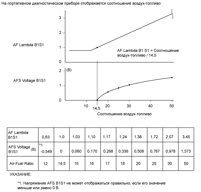
AFS Voltage B1S1 Tester Display Measurement Item/Range Normal Condition Type Cause of Out of Range AFS Voltage B1S1 Air fuel ratio sensor output voltage/
Min.: 0 V, Max.: 7.999 V
- -
-
Air fuel ratio sensor
-
Air fuel ratio sensor circuit
-
Injector assembly clogged
Diagnostic Note:
-
Check the air fuel ratio sensor output with the No. 2 exhaust gas temperature (Exhaust Temperature B1S2) at 200°C (392°F) or higher (example: driving at speed of 50 km/h (31 mph) or more in 3rd gear).
-
If the exhaust fuel addition injector is clogged, the AFS voltage B1S1 value changes according to engine combustion, but large changes due to the addition of fuel are not seen even when PM forced regeneration is performed with the GTS.
AFS Current B1S1 Tester Display Measurement Item/Range Normal Condition Type Cause of Out of Range AFS Current B1S1 Air fuel ratio sensor current/
Min.: -128 mA, Max.: 128 mA
- -
-
Air fuel ratio sensor
-
Air fuel ratio sensor circuit
-
Injector assembly clogged
Diagnostic Note:
-
Check the air fuel ratio sensor output with the No. 2 exhaust gas temperature (Exhaust Temperature B1S2) at 200°C (392°F) or higher (example: driving at speed of 50 km/h (31 mph) or more in 3rd gear).
-
If the exhaust fuel addition injector is clogged, even if PM forced regeneration is performed with the GTS, the AFS voltage B1S1 value will not change.
AF Sensor Learning Value Tester Display Measurement Item/Range Normal Condition Type Cause of Out of Range AF Sensor Learning Value Air fuel ratio sensor learning value/
Min.: 0 V, Max.: 5 V
- Value calculated by ECM - Diagnostic Note:
Inspect the air fuel ratio sensor performance.
Exhaust Temperature B1S1 Tester Display Measurement Item/Range Normal Condition Type Cause of Out of Range Exhaust Temperature B1S1 Exhaust gas temperature of DOC catalyst/
Min.: -40°C, Max.: 1000°C
-
Idling after engine warmed-up: 100 to 400°C (212 to 752°F)
-
During PM forced regeneration: 500 to 700°C (932 to 1292°F)
Sensor output (Exhaust gas temperature sensor)
-
Exhaust gas temperature sensor
-
DPF catalyst deteriorated
Diagnostic Note:
-
If an open occurs in an exhaust gas temperature sensor circuit, 0°C (32°F) is displayed on the GTS.
-
If a short occurs in an exhaust temperature sensor circuit, 1000°C (1832°F) or higher is displayed on the GTS.
Exhaust Temperature B1S2 Tester Display Measurement Item/Range Normal Condition Type Cause of Out of Range Exhaust Temperature B1S2 Exhaust gas temperature of upstream of the DPF catalyst/
Min.: -40°C, Max.: 1000°C
-
Idling after engine warmed-up: 100 to 400°C (212 to 752°F)
-
During PM forced regeneration: 500 to 700°C (932 to 1292°F)
Sensor output (No. 2 exhaust gas temperature sensor)
-
No. 2 exhaust gas temperature sensor
-
DPF catalyst deteriorated
Diagnostic Note:
-
If an open occurs in an No. 2 exhaust temperature sensor circuit, 0°C (32°F) is displayed on the GTS.
-
If a short occurs in an No. 2 exhaust temperature sensor circuit, 1000°C (1832°F) or higher is displayed on the GTS.
Exhaust Temperature B1S3 Tester Display Measurement Item/Range Normal Condition Type Cause of Out of Range Exhaust Temperature B1S3 Exhaust gas temperature of downstream of the DPF catalyst/
Min.: -40°C, Max.: 1000°C
-
Idling after engine warmed-up: 100 to 400°C (212 to 752°F)
-
During PM forced regeneration: 500 to 700°C (932 to 1292°F)
Sensor output (No. 3 exhaust gas temperature sensor)
-
No. 3 exhaust gas temperature sensor
-
DPF catalyst deteriorated
Diagnostic Note:
-
If an open occurs in an No .3 exhaust temperature sensor circuit, 0°C (32°F) is displayed on the GTS.
-
If a short occurs in an No. 3 exhaust temperature sensor circuit, 1000°C (1832°F) or higher is displayed on the GTS.
DPF Differential Pressure Tester Display Measurement Item/Range Normal Condition Type Cause of Out of Range DPF Differential Pressure DPF differential pressure/
Min.: -5 kPa, Max.: 100 kPa
Ignition switch ON:
Approximately 0 kPa
Sensor output (DPF differential pressure sensor)
-
DPF catalyst
-
DPF differential pressure sensor
-
Vacuum pipe clogged
-
Differential pressure sensor air hose clogged
Diagnostic Note:
-
When PM (Particulate Matter) builds up in the DPF catalyst, the "DPF Differential Pressure" value increases.
-
At 3000 rpm (no load), if Catalyst Differential Press is 0.27 or more, the DPF catalyst has become blocked.
Catalyst Differential Press Tester Display Measurement Item/Range Normal Condition Type Cause of Out of Range Catalyst Differential Press Amount of clogging in catalyst/
Min.: -4, Max.: 3.9998
0.27 or less Calculated value - Symptoms when out of range:
-
If the difference in pressure increases, a decrease in engine power may be felt.
-
If an abnormal difference in pressure is detected, engine power is limited to protect the engine and catalyst.
Diagnostic Note:
-
Diagnosis is possible when the MAF reading is between 30 and 140 gm/sec.
-
When the air intake volume is very low, such as when idling, due to excessive pressure fluctuation the correct values will not be displayed.
-
Catalyst Differential Press is the DPF Differential Pressure corrected in response to the MAF and other values.
-
If the filter in the DPF catalyst is clogged, the "Catalyst Differential Press" value increases.
-
When the difference in pressure exceeds approximately 0.27, DTC P244B is stored and "DPF PM Block" displays "Blocked".
Diff. Press. Sensor Corr. Tester Display Measurement Item/Range Normal Condition Type Cause of Out of Range Diff. Press. Sensor Corr. Differential pressure sensor 0 point learned value/
Min.: -10 kPa, Max.: 245.9 kPa
Ignition switch ON (engine stopped): -1.5 to 1.5 kPa - Differential pressure sensor Diagnostic Note
-
This number indicates the correction value (0 point calibration) for compensation of variance in the differential pressure sensor.
-
If the value of DPF Differential Pressure does not approach 0 kPa when the ignition switch is ON (engine is stopped) and the Diff. Press. Sensor Corr. displays less than -1.5 kPa or more than 1.5 kPa, there may be a malfunction in the differential pressure sensor.
-
Note that the output of the differential pressure sensor fluctuates depending on the temperature.
Exhaust Fuel Addition FB Tester Display Measurement Item/Range Normal Condition Type Cause of Out of Range Exhaust Fuel Addition FB Exhaust fuel addition correction value/
Min.: 0.8, Max.: 1.99
0.9 to 1.45 Value calculated by ECM
-
Exhaust fuel addition injector clogged
-
DPF catalyst deteriorated
Diagnostic Note
-
Usually Exhaust Fuel Addition FB is between 0.9 and 1.45.
-
Exhaust Fuel Addition FB is a correction value to increase the fuel volume injected from the exhaust fuel addition injector when the catalyst temperature does not rise to the target range during PM forced regeneration.
-
If the correction value is more than 1.45, a clog in the exhaust fuel addition injector assembly or fuel filter may be causing a reduction in injection volume or a problem with the engine (injectors, EGR, etc.) where the exhaust gas temperature decreases may be present. As a result, the catalyst temperature does not rise properly causing the catalyst to deteriorate.
DPNR/DPF Status Reju (PM) Tester Display Measurement Item/Range Normal Condition Type Cause of Out of Range DPNR/DPF Status Reju (PM) PM forced regeneration status/
Standby, Ready, Operate, Compl
During PM forced regeneration: Operate - - Diagnostic Note:
The status is only displayed while performing "Activate the DPF Rejuvenate (PM)".
-
Standby
-
Before entering the "Activate the DPF Rejuvenate (PM)".
-
Ready
-
Enabling condition for "Activate the DPF Rejuvenate (PM)" is not met.
-
Operate
-
PM forced regeneration is being performed.
-
If "Activate the DPF Rejuvenate (PM)" does not finish completely, the status turns to "Ready".
-
If "Activate the DPF Rejuvenate (PM)" finishes completely, the status turns to "Compl".
-
Compl
-
PM forced regeneration is completed.
PM Accumulation Ratio Tester Display Measurement Item/Range Normal Condition Type Cause of Out of Range PM Accumulation Ratio PM accumulation ratio/
Min.: 0%, Max.: 510%
- - - Diagnostic Note:
-
When PM forced regeneration is necessary, 100% is displayed for PM Accumulation Ratio.
-
If the ratio exceeds 100%, PM forced regeneration will be performed automatically
-
-
Diesel Exhaust 2
NOx Density B1S1 Tester Display Measurement Item/Range Normal Condition Type Cause of Out of Range NOx Density B1S1 Nitrogen oxides sensor/
Min.: 0 ppm, Max.: 65535 ppm
- - - Diagnostic Note:
Concentration of NOx in exhaust gas
NOx Density B1S2 Tester Display Measurement Item/Range Normal Condition Type Cause of Out of Range NOx Density B1S2 NOx density B1S2/
Min.: 0 ppm, Max.: 65535 ppm
- - - NOx Density B2S1 Tester Display Measurement Item/Range Normal Condition Type Cause of Out of Range NOx Density B1S3 NOx density B2S1/
Min.: 0 ppm, Max.: 65535 ppm
- - - NOx Density B2S2 Tester Display Measurement Item/Range Normal Condition Type Cause of Out of Range NOx Density B1S1 NOx density B2S2/
Min.: 0 ppm, Max.: 65535 ppm
- - - Comm with Reductant Control Module Tester Display Measurement Item/Range Normal Condition Type Cause of Out of Range Comm with Reductant Control Module Status of the comm with uria pump control ECU/
No Comm or Comm
- - - Diagnostic Note:
-
Reductant Level Tester Display Measurement Item/Range Normal Condition Type Cause of Out of Range Reductant Level Reductant level/
Min.: 0, Max.: 255
- - - Diagnostic Note:
Outputs the position of the urea solution inside the urea tank sub-assembly as a level from 0 to 6.
Reductant Temperature Tester Display Measurement Item/Range Normal Condition Type Cause of Out of Range Reductant Temperature Reductant temperature/
Min.: -40°C, Max.: 215°C
- - - Diagnostic Note:
Outputs the temperature of the urea solution inside the urea tank sub-assembly.
Reductant Pressure Tester Display Measurement Item/Range Normal Condition Type Cause of Out of Range Reductant Pressure Reductant pressure/
Min.: -3276.8 kPa, Max.: 3276.7 kPa
-50 to 600 kPa - - Diagnostic Note:
Outputs the pressure inside the urea pipe connecting the urea tank sub-assembly and urea injector set.
Reductant Pump Speed Tester Display Measurement Item/Range Normal Condition Type Cause of Out of Range Reductant Pump Speed Urea pump speed/
Min.: 0 rpm, Max.: 65535 rpm
0 to 3000 rpm - - Diagnostic Note:
Outputs the urea pump speed.
Reductant Injection Mode Tester Display Measurement Item/Range Normal Condition Type Cause of Out of Range Reductant Injection Mode Reductant injection mode/
-, Mode3
- - - Diagnostic Note:
Outputs the urea injector injection control mode.
Reductant Injection Value Tester Display Measurement Item/Range Normal Condition Type Cause of Out of Range Reductant Injection Value Reductant injection value/
Min.: 0 g/h, Max.: 3276.75 g/h
0 to 1800 g/h - - Diagnostic Note:
Outputs the urea solution injection volume.
Engine Exhaust NOx Density Tester Display Measurement Item/Range Normal Condition Type Cause of Out of Range Engine Exhaust NOx Density Engine exhaust NOx density/
Min.: 0 ppm, Max.: 65535 ppm
0 to 1650 ppm - - Diagnostic Note:
Outputs the concentration of NOx expelled from the engine.
SCR Temperature Tester Display Measurement Item/Range Normal Condition Type Cause of Out of Range SCR Temperature Exhaust gas temperature of SCR catalyst/
Min.: -40, Max.: 6513.5°C
50 to 400°C (122 to 752°F) - - Diagnostic Note:
-
Outputs the temperature at the center of the SCR catalyst.
-
The temperature value displays the output of the No. 4 exhaust gas temperature sensor.
Catalyst Thermal Degradation Count Tester Display Measurement Item/Range Normal Condition Type Cause of Out of Range Catalyst Thermal Degradation Count Catalyst thermal degradation count/
Min.: 0, Max.: 4294967295
- - - Diagnostic Note:
The count increases when the catalyst (DPF) temperature exceeds 500°C. The count is reset by the "DPR Deterioration History Initialization" item in the Utility menu.
Reductant Injection Value Restraint Control Tester Display Measurement Item/Range Normal Condition Type Cause of Out of Range Reductant Injection Value Restraint Control Reductant injection value restraint control/
ON or OFF
- - - Diagnostic Note:
Turns ON when the necessary urea solution injection volume is high and the quantity of urea consumption does not meet the target value. (Urea solution injection volume restraint is performed.)
SCR NOx Purge High Efficiency Temp Tester Display Measurement Item/Range Normal Condition Type Cause of Out of Range SCR NOx Purge High Efficiency Temp SCR NOx purge high efficiency temp/
ON or OFF
- - - Diagnostic Note:
Turns ON when the SCR catalyst reaches a temperature that allows the Urea SCR system to demonstrate high NOx purification efficiency.
NOx Sensor Active Status Tester Display Measurement Item/Range Normal Condition Type Cause of Out of Range NOx Sensor Active Status Nitrogen oxides sensor active status/
ON or OFF
- - - Diagnostic Note:
Turns ON when the nitrogen oxides sensor meets or exceeds a set temperature and becomes capable of stable output.
Reductant Tank Heater Tester Display Measurement Item/Range Normal Condition Type Cause of Out of Range Reductant Tank Heater Urea tank heater status/
ON or OFF
- - - Diagnostic Note:
Outputs the operation status of the urea tank heater.
Reductant Pipe Heater Tester Display Measurement Item/Range Normal Condition Type Cause of Out of Range Reductant Pipe Heater Urea tube with heater assembly heater status/
ON or OFF
- - - Diagnostic Note:
Outputs the operation status of the Urea tube with heater assembly.
NOx Sensor Cooling Time Tester Display Measurement Item/Range Normal Condition Type Cause of Out of Range NOx Sensor Cooling Time Nitrogen oxides sensor cooling time/
Min.: 0 sec, Max.: 65535 sec
- - - Diagnostic Note:
Outputs the amount of time that has elapsed since the nitrogen oxides sensor heater turned OFF.
-
-
Diesel Starting
Engine Speed (Starter Off) Tester Display Measurement Item/Range Normal Condition Type Cause of Out of Range Engine Speed (Starter Off) Engine speed when starter off/
Min.: 0 rpm, Max.: 1594 rpm
- - - Diagnostic Note:
Engine speed immediately after starting the engine.
Starter Count Tester Display Measurement Item/Range Normal Condition Type Cause of Out of Range Starter Count Starter on count/
Min.: 0, Max.: 255
- - - Diagnostic Note:
Number of times the starter turned on from the time the ignition switch was turned to ON.
Run Dist of Previous Trip Tester Display Measurement Item/Range Normal Condition Type Cause of Out of Range Run Dist of Previous Trip Distance driven during previous trip/
Min.: 0 km, Max.: 261 km
- - - Diagnostic Note:
Before 5 seconds elapse after starting the engine, which is the DTC P1604 (Startability Malfunction) detection duration, this parameter indicates the distance driven during the previous trip. After 5 seconds elapse after starting the engine, this parameter indicates the distance driven during the current trip calculated from the vehicle speed signal.
Tech Tips
-
Run Dist of Previous Trip in the freeze frame data present when the startability malfunction occurred (DTC P1604 detected) indicates the distance driven during the previous trip, but in all other cases, such as for the snapshot data of the Data List (real-time measurements), or for freeze frame data present when DTCs other than P1604 were detected, the value indicates the distance driven during the current trip.
-
If DTCs indicating insufficient power or problems with the DPF system, diesel throttle or EGR valve are stored, confirm this item in the freeze frame data of the stored DTCs to determine the distance driven when the DTCs were stored. The distance driven can be used as a reference when troubleshooting.
Glow Request Lighting Time Tester Display Measurement Item/Range Normal Condition Type Cause of Out of Range Glow Request Lighting Time Glow request lighting time/
Min.: 0 ms, Max.: 33423 ms
- - - Diagnostic Note:
-
By comparing Glow Request Lighting Time to IG-ON Time, the operation state (whether the engine was started, etc.) can be determined.
-
If the malfunction occurred when starting a cold engine at 0°C (32°F) or less, this item is useful in determining whether the engine was started after the glow plug indicator lights turned off.
IG-ON Time Tester Display Measurement Item/Range Normal Condition Type Cause of Out of Range IG-ON Time IG-ON time/
Min.: 0 ms, Max.: 33423 ms
- - - Diagnostic Note:
-
By comparing Glow Request Lighting Time to IG-ON Time, the operation state (whether the engine was started, etc.) can be determined.
-
If the malfunction occurred when starting a cold engine at 0°C (32°F) or less, this item is useful in determining whether the engine was started after the glow plug indicator lights turned off.
Immobiliser Fuel Cut History Tester Display Measurement Item/Range Normal Condition Type Cause of Out of Range Immobiliser Fuel Cut History Immobiliser fuel cut history/
ON or OFF
OFF - - Diagnostic Note:
If Immobiliser Fuel Cut History was "ON" when DTC P1604 (Startability Malfunction) was stored, the engine could not be started due to the immobiliser.
-
-
Diesel Rough Idle
Compression Leakage Count Tester Display Measurement Item/Range Normal Condition Type Cause of Out of Range Compression Leakage Count Compression leakage count/
Min.: 0, Max.: 255
0 - - Diagnostic Note:
When the counter displays 1 or higher during an engine stall, startability malfunction or rough idle, it may be the result of pressure loss caused by deposits jamming the valve, etc.
Plural Cylinders Rough Idle Tester Display Measurement Item/Range Normal Condition Type Cause of Out of Range Plural Cylinders Rough Idle Status of the plural cylinders rough idle/
ON or OFF
OFF - - Diagnostic Note:
Indicates multiple cylinders are the cause of rough idling when ON.
EGR Rate Differential(Actual-Target) Tester Display Measurement Item/Range Normal Condition Type Cause of Out of Range EGR Rate Differential(Actual-Target) Difference between actual EGR and target EGR while idling/
Min.: -128%, Max.: 127%
- - - Diagnostic Note:
-
Percentage value (-100 to 100%), calculated as (Actual EGR - Target EGR) * 100 is displayed.
-
The maximum value is retained once idling is stabilized. Once the vehicle is no longer idling, such as when the vehicle is accelerated, the value resets to 0%.
-
A positive value indicates a large amount of EGR and a negative value indicates a small amount of EGR.
Rough Idle #1 / Rough Idle #2 / Rough Idle #3 / Rough Idle #4 Tester Display Measurement Item/Range Normal Condition Type Cause of Out of Range Rough Idle #1
Rough Idle #2
Rough Idle #3
Rough Idle #4
Status of the rough idle #1 to #4/
ON or OFF
OFF - Injector assembly Diagnostic Note:
-
This item indicates cylinders which had speeds lower than the other cylinders.
-
This item indicates cylinders which are likely to be the cause of rough idle.
Electric Duty Feedback Value Tester Display Measurement Item/Range Normal Condition Type Cause of Out of Range Electric Duty Feedback Value Electric load feedback value/
Min.: 0 mm3/st, Max.: 39.8 mm3/st
0 to 7 mm3/st
- - Diagnostic Note:
Expected injection volume increase after the electrical load turns from off to on.
A/C Duty Feedback Value Tester Display Measurement Item/Range Normal Condition Type Cause of Out of Range A/C Duty Feedback Value A/C load feedback value/
Min.: 0 mm3/st, Max.: 39.8 mm3/st
0 to 3.3 mm3/st
- - Diagnostic Note:
Expected injection volume increase after the A/C turns from off to on.
PS Duty Feedback Value Tester Display Measurement Item/Range Normal Condition Type Cause of Out of Range PS Duty Feedback Value Power steering load feedback value/
Min.: 0 mm3/st, Max.: 39.8 mm3/st
0 mm3/st
- - Diagnostic Note:
Expected injection volume increase after the power steering turns from off to on.
-
-
Diesel Power
MAF Low Tester Display Measurement Item/Range Normal Condition Type Cause of Out of Range MAF Low Mass air flow Low/
ON or OFF
OFF -
-
Mass air flow meter sub-assembly (value is out of range)
-
Intake system blockage
-
Disconnected air hoses (intake system)
-
EGR system (EGR valve closing malfunction)
-
Nozzle vane (turbo) movement problems
Symptoms when out of range:
Lack of power
Diagnostic Note:
-
When DTC P1608 is output, this item indicates whether the cause of lack of power is related to the intake air amount.
-
This item indicates whether the intake air amount measured by the mass air flow meter sub-assembly was insufficient, which would cause the fuel injection volume to be reduced for a certain period of time. If this is the case, this item displays "ON" and DTC P1608 (lack of engine power) is stored.
-
This item is "ON" when the intake air amount is low due to blockage in the intake system, disconnection of hoses or an excessive amount of EGR, and also when the intake air amount is measured to be low due to deterioration of the mass air flow meter sub-assembly.
Boost Pressure Low Tester Display Measurement Item/Range Normal Condition Type Cause of Out of Range Boost Pressure Low Status of the Boost Pressure Low/
ON or OFF
OFF -
-
Nozzle vane (turbo) stuck
-
Disconnected air hoses (intake system)
-
Manifold absolute pressure sensor
-
Atmospheric pressure sensor (built into ECM)
-
Difference between atmospheric pressure and intake pressure
Symptoms when out of range:
Lack of power
Diagnostic Note:
-
When DTC P1608 is output, this item indicates whether the cause of lack of power is due to the boost pressure.
-
This item indicates whether the actual boost pressure was insufficient compared to the target boost pressure, which would cause the fuel injection volume to be reduced for a certain period of time. If this is the case, this item displays "ON" and DTC P1608 (lack of engine power) is stored.
Common Rail Pressure Low Tester Display Measurement Item/Range Normal Condition Type Cause of Out of Range Common Rail Pressure Low Status of the common rail pressure low/
ON or OFF
OFF -
-
Suction control valve (movement problems)
-
Fuel leak
-
Fuel pressure sensor (built into common rail assembly)
Symptoms when out of range:
Lack of power
Diagnostic Note:
-
When DTC P1608 is output, this item indicates whether the cause of lack of power is the common rail pressure.
-
This item indicates whether the actual common rail pressure was lower than the target pressure for a certain period of time. If this is the case, this item displays "ON" and DTC P1608 (lack of engine power) is stored.
Engine Coolant Temp High Tester Display Measurement Item/Range Normal Condition Type Cause of Out of Range Engine Coolant Temp High Status of the engine coolant temp high/
ON or OFF
OFF -
-
Engine coolant temperature sensor
-
Engine coolant leak
-
Radiator clog
Symptoms when out of range:
Lack of power
Diagnostic Note:
-
When DTC P1608 is output, this item indicates whether the cause of lack of power is due to a high engine coolant temperature.
-
This item indicates whether the fuel injection volume was reduced for a certain period of time due to a high engine coolant temperature (overheating). If this is the case, this item displays "ON" and DTC P1608 (lack of engine power) is stored.
MAF/Estimate MAF Ratio Tester Display Measurement Item/Range Normal Condition Type Cause of Out of Range MAF/Estimate MAF Ratio Ratio of intake air amount to estimated intake air amount/
Min.: 0, Max.: 2.55
Engine speed 4000 rpm, EGR system off:
0.6 to 1.4
-
-
Mass air flow meter sub-assembly
-
Turbocharger sub-assembly
-
Pipes between turbocharger sub-assembly and intake manifold are disconnected or leaking
-
Pipes between mass air flow meter sub-assembly and turbocharger sub-assembly are disconnected or leaking
Symptoms when out of range:
Lack of power
Diagnostic Note:
-
Even when the system is normal, the value may deviate from the range specified in Normal Condition for a short period of time (approximately 1 second).
-
This item indicates the ratio of the intake air amount to the estimated intake air amount. The estimated air amount is calculated using the intake manifold pressure and intake air temperature.
-
When DTC P1608 is stored, this item is useful in determining whether there is a problem in the turbocharger system or a disconnected or leaking pipe in the high pressure intake system when the boost pressure is insufficient.
-
When performing troubleshooting, this information is only valid when there is a high load (the diesel throttle is fully open) and the EGR system is off.
-
-
Monitor Result/Stet result
Monitor Information Tester Display Measurement Item/Range Normal Condition Diagnostic Note Complete Parts Monitor Comprehensive component monitor/
Not Avl or Avail
- *1 Fuel System Monitor Fuel system monitor/
Not Avl or Avail
- *1 Misfire Monitor Misfire monitor/
Not Avl or Avail
- *1 EGR/VVT Monitor EGR/VVT monitor
Not Avl or Avail/
- *1 EGR/VVT Monitor EGR/VVT monitor
Compl or Incmpl
- *1 O2S(A/FS) Heater Monitor O2S(A/FS) heater monitor/
Not Avl or Avail
- *1 O2S(A/FS) Heater Monitor O2S(A/FS) heater monitor/
Compl or Incmpl
- *1 O2S(A/FS) Monitor O2S(A/FS) monitor/
Not Avl or Avail
- *1 O2S(A/FS) Monitor O2S(A/FS) monitor/
Compl or Incmpl
- *1 A/C Monitor A/C monitor/
Not Avl or Avail
- *1 A/C Monitor A/C monitor/
Compl or Incmpl
- *1 2nd Air Monitor 2nd air monitor/
Not Avl or Avail
- *1 2nd Air Monitor 2nd air monitor/
Compl or Incmpl
- *1 EVAP Monitor EVAP monitor/
Not Avl or Avail
- *1 EVAP Monitor EVAP monitor/
Compl or Incmpl
- *1 Heated Catalyst Monitor Heated catalyst monitor/
Not Avl or Avail
- *1 Heated Catalyst Monitor Heated catalyst monitor/
Compl or Incmpl
- *1 Catalyst Monitor Catalyst monitor/
Not Avl or Avail
- *1 Catalyst Monitor Catalyst monitor/
Compl or Incmpl
- *1 *1:
Avail: The monitor is available on the vehicle.
Not Avl: The monitor is not available on the vehicle.
Incmpl / Compl: The item changes from Incmpl to Compl if the monitor was completed at least once at some time in the past. This item does not change when the ignition switch is turned off. However, the item changes back to Incmpl when DTCs are cleared or the battery cable is disconnected.
Test Result Tester Display Measurement Item/Range Normal Condition Diagnostic Note SPD Test Result Check mode result for vehicle speed sensor/
Compl or Incmpl
- *1 Exhaust Temperature B1S1 Test Result Check mode result for exhaust temperature B1S1/
Compl or Incmpl
- *1 Exhaust Temperature B1S2 Test Result Check mode result for exhaust temperature B1S2/
Compl or Incmpl
- *1 Exhaust Temperature B1S3 Test Result Check mode result for exhaust temperature B1S3/
Compl or Incmpl
- *1 Exhaust Temperature B1S4 Test Result Check mode result for exhaust temperature B1S4/
Compl or Incmpl
- *1 *1:
Incmpl / Compl: The item changes from Incmpl to Compl if the monitor was completed at least once at some time in the past. This item does not change when the ignition switch is turned off. However, the item changes back to Incmpl when DTCs are cleared or the battery cable is disconnected.
-
Support Data (Monitor Support Status)
Support Data Tester Display Measurement Item/Range Normal Condition Diagnostic Note Intake Air Temp (Turbo) Supported Intake air temp (Turbo) support/
Unsupp or Supp
- *1 NOx Density B1S1 Supported NOx density B1S1 support/
Unsupp or Supp
- *1 NOx Density B1S2 Supported NOx density B1S2 support/
Unsupp or Supp
- *1 NOx Density B2S1 Supported NOx density B2S1 support/
Unsupp or Supp
- *1 NOx Density B2S2 Supported NOx density B2S2 support/
Unsupp or Supp
- *1 Glow Indicator Supported Glow indicator Support/
Unsupp or Supp
- *1 Target Throttle Position Supported Target throttle position support/
Unsupp or Supp
- *1 Target Throttle Position #2 Supported Target throttle position (No. 2) Support/
Unsupp or Supp
- *1 Actual Throttle Position Supported Actual throttle position support/
Unsupp or Supp
- *1 Actual Throttle #2 Position Supported Actual throttle (No. 2) position support/
Unsupp or Supp
- *1 Target Common Rail Pressure Supported Target common rail pressure support/
Unsupp or Supp
- *1 Common Rail Pressure Supported Common rail pressure support/
Unsupp or Supp
- *1 Fuel Temperature Supported Fuel temperature support/
Unsupp or Supp
- *1 Target EGR Valve Pos Supported Target EGR valve pos support/
Unsupp or Supp
- *1 Target EGR Valve Pos #2 Supported Target EGR valve pos (No. 2) support/
Unsupp or Supp
- *1 Actual EGR Valve Pos Supported Actual EGR valve pos support/
Unsupp or Supp
- *1 Actual EGR Valve Pos #2 Supported Actual EGR valve pos (No. 2) support/
Unsupp or Supp
- *1 Target Booster Pressure Supported Target booster pressure supported/
Unsupp or Supp
- *1 VN Turbo Command Supported VN turbo command supported/
Unsupp or Supp
- *1 VN Turbo Command #2 Supported VN turbo command (No. 2) supported/
Unsupp or Supp
- *1 Actual VN Position Supported Actual VN position supported/
Unsupp or Supp
- *1 Actual VN Position #2 Supported Actual VN position (No. 2) supported/
Unsupp or Supp
- *1 Exhaust Temperature B1S1 Supported Status of exhaust temperature B1S1 supported/
Unsupp or Supp
- *1 Exhaust Temperature B1S2 Supported Status of exhaust temperature B1S2 supported/
Unsupp or Supp
- *1 Exhaust Temperature B1S3 Supported Status of exhaust temperature B1S3 supported/
Unsupp or Supp
- *1 DPF Differential Pressure Supported DPF differential pressure supported/
Unsupp or Supp
- *1 *1:
Supp: The item is supported by the vehicle.
Unsupp: The monitor is not supported by the vehicle.
-
AT (for Automatic Transmission)
Received MIL from ECT Tester Display Measurement Item/Range Normal Condition Type Cause of Out of Range Received MIL from ECT MIL status from ECT/
ON or OFF
ON: MIL ON - - Communication with ECT Tester Display Measurement Item/Range Normal Condition Type Cause of Out of Range Communication with ECT Communication with ECT/
Comm or No Comm
- - - Shift Position Sig from ECT Tester Display Measurement Item/Range Normal Condition Type Cause of Out of Range Shift Position Sig from ECT Shift position signal from ECT/
1st, 2nd, 3rd, 4th, 5th or 6th
- - - A/T Oil Temp from ECT Tester Display Measurement Item/Range Normal Condition Type Cause of Out of Range A/T Oil Temp from ECT ATF temperature from ECT/
Min.: -40°C, Max.: 215°C
With engine cold: Equal to ambient temperature - - SPD (NO) Tester Display Measurement Item/Range Normal Condition Type Cause of Out of Range SPD (NO) Output shaft speed/
Min.: 0 rpm, Max.: 12750 rpm
- - - ECT Lock Up Tester Display Measurement Item/Range Normal Condition Type Cause of Out of Range ECT Lock Up Lock-up/
ON or OFF
ON: Lock-up operating - - A/T Oil Temperature 1 Tester Display Measurement Item/Range Normal Condition Type Cause of Out of Range A/T Oil Temperature 1 ATF temperature sensor value/
Min.: -40°C, Max.: 215°C
With engine cold:
Equal to ambient temperature
- - Diagnostic Note:
If the value is -40°C (-40°F) or 150°C (302°F), the ATF temperature sensor circuit is open or shorted.
-
ACTIVE TEST
Tech Tips
Using the GTS to perform Active Tests allows relays, VSVs, actuators and other items to be operated without removing any parts. This non-intrusive functional inspection can be very useful because intermittent operation may be discovered before parts or wiring is disturbed. Performing Active Tests early in troubleshooting is one way to save diagnostic time. Data List information can be displayed while performing Active Tests.
-
Connect the GTS to the DLC3.
-
Turn the ignition switch to ON.
-
Turn the GTS on.
-
Enter the following menus: Powertrain / Engine and ECT / Active Test.
-
Perform the Active Test.
Tester Display Test Part Control Range Diagnostic Note Activate the VSV for Swirl Control Valve Activate the vacuum switching valve assembly (for swirl control valve) ON/OFF Test is possible when the following conditions are met:
-
Ignition switch ON.
-
Engine running (warmed up).
Control the A/C Cut Signal Control the A/C cut signal ON/OFF - Control the ACM Inhibit Activate vacuum switching valve sub-assembly (for engine mounting) ON/OFF - Connect the TC and TE1 Turn on the TC and TE1(CG) connection ON/OFF - Control the Electric Cooling Fan Control the electric cooling fan operation ON/OFF Test is possible when the following conditions are met:
-
Ignition switch ON.
-
Engine is stopped.
Control the EGR Step Position Control the electric EGR control valve assembly 1 to 100% Test is possible when the following conditions are met:
-
Ignition switch ON.
-
Engine is stopped.
Activate the VN Turbo Cleaning Activate the VN turbo cleaning ON/OFF Perform this test when the following conditions are met:
-
Ignition switch is ON.
-
Engine running (warmed up).
-
Engine Coolant Temperature 77°C (171°F) or higher
Activate the DPF Rejuvenate (PM) PM forced regeneration Raise temperature of DPF to more than 600°C (1112°F) by adding fuel intermittently using the exhaust fuel addition injector ON/OFF Diesel Throttle Target Angle Control the diesel throttle valve 10 to 100% Test is possible when the following conditions are met:
-
Ignition switch ON.
-
Engine is stopped.
Test the Turbo Charger Step Motor Activate the turbocharger sub-assembly 0 to 60% Test is possible when the following conditions are met:
-
Ignition switch ON.
-
Engine is stopped.
Test the Fuel Leak Pressurize the common rail interior and check for fuel leaks Stop/Start
-
Fuel pressure inside common rail pressurized to specified value and engine speed increased to 2000 rpm when ON is selected
-
Above conditions preserved while test is ON
Tech Tips
If this Active Test is performed when the engine is cold, combustion may become unstable. However, this is not a malfunction. It is only necessary to confirm that the pressure rises to the target pressure and that there are no fuel leaks.
Activate the Pre-stroke Control Valve Activates the pre-stroke control valve Open/Close Test is possible when the following conditions are met:
-
Ignition switch ON.
-
Engine is stopped.
Activate the VN Turbo Open Activate the turbocharger Open/OFF Confirm that the engine is running. Activate the EGR Valve Close Activate the electric EGR control valve assembly ON/OFF Confirm that the vehicle is stopped and the engine is idling Activate the VSV for EGR Cooler Bypass Activate the No. 1 vacuum switching valve assembly (for EGR bypass valve) Bypass/Half Pos/Cooler Test is possible when the following conditions are met:
-
Engine warmed up
-
Engine is idling
-
Shift lever in neutral
If performing the Active Test continuously, it must be finished within 5 minutes.
Control the Select Cylinder Fuel Cut Selected cylinder (cylinder #1 to #4) injector assembly fuel cut #1/#2/#3/#4
ON/OFF
Fuel injection is stopped while the test is ON.
-
Confirm that the vehicle is stopped and the engine is idling.
-
If the running condition of the engine does not worsen even though injection of the designated cylinder is stopped, the cylinder can be determined to be malfunctioning.
Check the Cylinder Compression* Check the cylinder compression pressure ON/OFF Fuel injection stops in all cylinders. Reductant Injection Valve Activates the urea injection set Open/Close Test is possible when the following conditions are met:
-
Ignition switch ON
-
Shift lever in neutral
-
Ambient temperature 0°C or higher
Tech Tips
This test can be used to confirm the operating noise of the urea injection set.
Reductant Pipe Heater Activates the urea tube with heater assembly ON/OFF Test is possible when the following conditions are met:
-
Ignition switch ON
-
Shift lever in neutral
-
Ambient temperature 0°C or higher
Tech Tips
-
Operation time is 30 seconds
-
Cannot be operated again for 20 seconds
Reductant Tank Heater Activates the urea tank heater ON/OFF Test is possible when the following conditions are met:
-
Ignition switch ON
-
Shift lever in neutral
-
Ambient temperature 0°C or higher
-
Urea solution level is at 2 or higher
Tech Tips
-
Operation time is 30 seconds
-
Cannot be operated again for 20 seconds
Reductant Discharge Activates the reductant discharge ON/OFF Test is possible when the following conditions are met:
-
Ignition switch ON
-
Shift lever in neutral
-
Ambient temperature 0°C or higher
Reductant Filling (Pressure Keep) Activates the reductant filling (pressure keep) ON/OFF Test is possible when the following conditions are met:
-
Ignition switch ON
-
Shift lever in neutral
-
Ambient temperature 0°C or higher
Tech Tips
-
After filling Urea solution to the Urea line, raise the pressure of the Urea to 500 kPa.
-
Used by itself:
Check for urea solution leaks by raising the pressure.
-
Used in combination:
Urea injection is possible if "Reductant Injection Valve" is executed after the completion of this operation.
Reductant Pump Check (Backward) Activates the urea pump check ON/OFF Test is possible when the following conditions are met:
-
Ignition switch ON
-
Shift lever in neutral
-
Ambient temperature 0°C or higher
Tech Tips
-
Operate the pump in reverse to check that it can operate.
-
When performing a forced operation of the pump, first be sure to complete "Reductant Pump Check (Backward)" and check that the pump operates normally.
Reductant Purge Activates the reductant purge ON/OFF Test is possible when the following conditions are met:
-
Ignition switch ON
-
Shift lever in neutral
-
Ambient temperature 0°C or higher
Tech Tips
Operate the pump in reverse and open the urea injection valve in order to draw the urea solution back into the pump from the urea line.
-
Tech Tips
*: When cranking the engine, the Active Test measures the speed of each cylinder. In this Active Test, the fuel of all cylinders is cut when the engine is cranked for approximately 10 seconds.
At this time, the speed of each cylinder is measured. If the speed of one cylinder is more than the other cylinders, it can be determined that the compression pressure of that cylinder is lower than the other cylinders.
-
Warm up the engine.
-
Turn the ignition switch off.
-
Connect the GTS to the DLC3.
-
Turn the ignition switch to ON and turn the GTS on.
-
Enter the following menus: Powertrain / Engine and ECT / Active Test / Check the Cylinder Compression.
Tech Tips
If the results are not displayed normally, select the display items from the Data List before performing the Active Test. Enter the following menus: Powertrain / Engine and ECT / Data List / Compression / Engine Speed of Cyl #1, Engine Speed of Cyl #2, Engine Speed of Cyl #3, Engine Speed of Cyl #4 and Av Engine Speed of All Cyl.
-
While the engine is not running, press the RIGHT or LEFT button to change Check the Cylinder Compression to ON.
Tech Tips
After performing the above procedure, the "Check the Cylinder Compression" Active Test will start. Fuel injection for all cylinders is prohibited and the engine speed measurement of each cylinder enters standby mode.
-
Crank the engine for about 10 seconds.
-
Monitor the engine speed (Engine Speed of Cyl #1 to #4, Av Engine Speed of All Cyl) displayed on the GTS.
Tech Tips
At first, the GTS display will show the engine speed measurement of each cylinder to be extremely high. After approximately 10 seconds of engine cranking, the engine speed measurement of each cylinder will change to the actual engine speed.
Note
-
After the "Check the Cylinder Compression" Active Test is turned on, it will automatically turn off after 255 seconds.
-
When the "Check the Cylinder Compression" test is off and the engine is cranked, the engine will start.
-
If the "Check the Cylinder Compression" test needs to be performed after it is turned on and performed once, press "EXIT" to return to the Active Test menu screen. Then perform the "Check the Cylinder Compression" test again.
-
Use a fully-charged battery.
-
-
-
SYSTEM CHECK
-
Connect the GTS to the DLC3.
-
Turn the ignition switch to ON.
-
Turn the GTS on.
-
Enter the following menus: Powertrain / Engine and ECT / Utility.
Tester Display Test Part Control Range Diagnostic Note Pressure Discharge Valve Check* Perform pressure discharge valve operation ON/OFF
-
Malfunctions can be determined by checking the fuel pressure when performing a forced operation of the pressure discharge valve.
-
Use when troubleshooting fuel pressure control malfunctions and abnormal combustion noise.
NOx Sensor Check Check the nitrogen oxides sensor output ON/OFF - Reductant Injection Valve Check Perform Urea injector operation ON/OFF Test is possible when the following conditions are met:
-
Ignition switch ON
-
Shift lever in neutral
-
Ambient temperature 0°C or higher
Tech Tips
-
This test is used to perform operations from urea solution refueling up to injection and determine urea injection set malfunctions (stuck open/closed, spray direction).
-
Perform this test according to the troubleshooting procedure.
-
-
*: Activate the Pressure Discharge Valve Check
Tech Tips
-
This is the procedure for troubleshooting fuel pressure control malfunctions and combustion problems.
-
Malfunctions can be determined by checking the fuel pressure when performing a fuel cut and operating the pressure discharge valve with the GTS.
-
During "Pressure Discharge Valve Check", the GTS measures the fuel pressure while the engine is running, after the engine is stopped, and after the pressure discharge valve operates.
-
Connect the GTS to the DLC3.
-
Turn the ignition switch to ON.
-
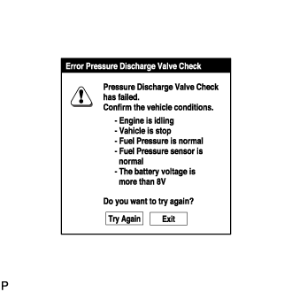
Turn the GTS on.
Note
Confirm the following conditions:
-
Engine is idling.
-
Vehicle is stopped.
-
Fuel pressure is not extremely high (below 100 MPa).
-
Fuel pressure is not extremely low (higher than 26 MPa).
-
Fuel pressure sensor is normal.
-
Battery voltage is higher than 8 V.
Tech Tips
When the common rail pressure is unstable, the fuel pressure may decrease to a level where the test cannot be performed. In this situation, wait until the common rail pressure meets the test condition, and then perform the test.
-
-
Enter the following menus: Powertrain / Engine and ECT / Utility / Pressure Discharge Valve Check.
-
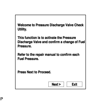
Press "Next".
-
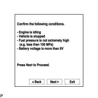
Press "Next" again to proceed.
-
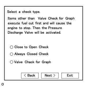
Select the check type "Valve Check for Graph".
-
Press "Next" again to proceed.
-
Press "Start" again to proceed.
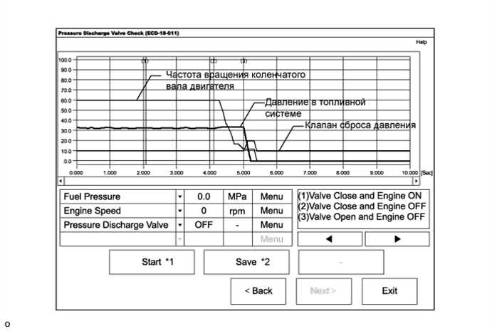
*1: When "Start" is pressed, the pressure discharge valve check begins.
*2: If "Save" is pressed after the pressure discharge valve check, the data recorded during the valve check can be saved.
-
-
Select the check type "Close to Open Check" or "Always Closed Check".
Tech Tips
-
"Close to Open Check" opens the pressure discharge valve after the engine stops.
-
"Always Closed Check" holds the pressure discharge valve closed during the check.
-
Press "Next".
-
Perform troubleshooting based on the measurement results.
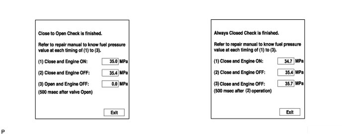
Tech Tips
-
During "Close to Open Check", if there is no large change in fuel pressure when the pressure discharge valve is closed while the engine is running and after the engine is stopped, and if the value is 0 kPa when the pressure discharge valve is open, the system is normal.
-
Perform "Always Closed Check" if the value is not 0 kPa when the pressure discharge valve is open during "Close to Open Check". If the results are the same as during "Close to Open Check", there is a pressure discharge valve operation malfunction.
-
If the fuel temperature is high, perform "Pressure Discharge Valve Check" after the fuel has cooled to the outside air temperature.
-
If a large amount of fuel is leaking, the fuel pressure decreases when the engine is stopped. However, the condition of the pressure discharge valve can still be determined by comparing the measurement results of "Close to Open Check" and "Always Closed Check".
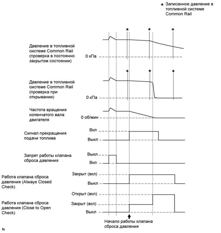
-
-
-
-