СИСТЕМА SFI, Diagnostic DTC:P2237, P2238, P2239, P2252, P2253
| DTC Code | DTC Name |
|---|---|
| P2237 | Oxygen (A/F) Sensor Pumping Current Circuit / Open (Bank 1 Sensor 1) |
| P2238 | Oxygen (A/F) Sensor Pumping Current Circuit Low (Bank 1 Sensor 1) |
| P2239 | Oxygen (A/F) Sensor Pumping Current Circuit High (Bank 1 Sensor 1) |
| P2252 | Oxygen (A/F) Sensor Reference Ground Circuit Low (Bank 1 Sensor 1) |
| P2253 | Oxygen (A/F) Sensor Reference Ground Circuit High (Bank 1 Sensor 1) |
DESCRIPTION
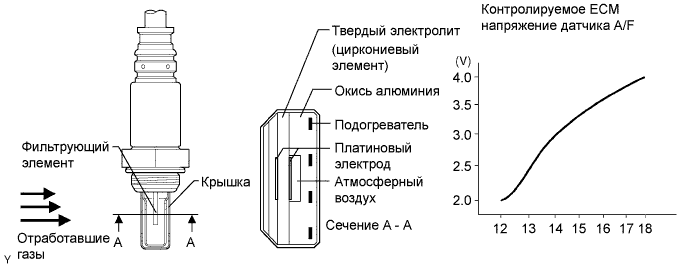
The air fuel ratio sensor generates a voltage* that corresponds to the actual air-fuel ratio. This sensor voltage is used to provide the ECM with feedback so that it can control the air-fuel ratio. The ECM determines the deviation from the stoichiometric air-fuel ratio and regulates the fuel injection time. If the air fuel ratio sensor malfunctions, the ECM is unable to control the air-fuel ratio accurately.
The air fuel ratio sensor is of the planar type and is integrated with a heater, which heats the solid electrolyte (zirconia element). This heater is controlled by the ECM. When the intake air volume is low (the exhaust gas temperature is low), a current flows through the heater to heat the sensor in order to facilitate accurate air-fuel ratio detection. In addition, the sensor and heater portions are the narrow type. The heat generated by the heater is conducted to the solid electrolyte through the alumina, thereby accelerating the sensor activation.
In order to obtain a high purification rate of the carbon monoxide (CO), hydrocarbon (HC) and nitrogen oxide (NOx) components in the exhaust gas, a Three-Way Catalytic Converter (TWC) is used. For the most efficient use of the Three-Way Catalytic Converter (TWC), the air-fuel ratio must be precisely controlled so that it is always close to the stoichiometric level.
*: The value changes inside the ECM. Since the air fuel ratio sensor is a current output element, the current is converted into a voltage inside the ECM. Any measurements taken at the air fuel ratio sensor or ECM connectors will show a constant voltage.
| DTC No. | DTC Detection Condition | Trouble Area |
|---|---|---|
| P2237 | Open in the circuit between terminals AF+ and AF- of the air fuel ratio sensor while the engine is running (2 trip detection logic). |
|
| P2238 |
Condition (a) or (b) continues for 5.0 seconds or more (2 trip detection logic): (a) AF+ voltage is 0.5 V or less. (b) (AF+) - (AF-) is 0.1 V or less.
Air fuel ratio sensor admittance is below 0.021 1/Ω (2 trip detection logic). |
|
| P2239 | AF+ voltage is higher than 4.5 V for 5.0 seconds or more (2 trip detection logic). |
|
| P2252 | AF- voltage is 0.5 V or less for 5.0 seconds or more (2 trip detection logic). |
|
| P2253 | AF- voltage is higher than 4.5 V for 5.0 seconds or more (2 trip detection logic). |
|
MONITOR DESCRIPTION
These DTCs are output when there is an open or short in the air fuel ratio sensor circuit, or if the air fuel ratio sensor output drops.
To detect these problems, the voltage of the air fuel ratio sensor is monitored when turning the ignition switch to ON, and the admittance (admittance is an electrical term that indicates the ease of flow of current) is checked while driving. If the voltage of the air fuel ratio sensor is between 0.6 V and 4.5 V, it is considered normal. If the voltage is outside of the specified range, or the admittance is below the standard value, the ECM will determine that there is a malfunction in the air fuel ratio sensor. If the same malfunction is detected in the next driving cycle, the MIL is illuminated and a DTC is stored.
The air fuel ratio sensor varies its output voltage in proportion to the air-fuel ratio. If the air fuel ratio sensor impedance (alternating current resistance) or output voltage deviates greatly from the standard range, the ECM determines that there is an open or short in the air fuel ratio sensor circuit.
MONITOR STRATEGY
| Required Sensors/Components | Air fuel ratio sensor |
| Frequency of Operation | Continuous |
CONFIRMATION DRIVING PATTERN
-
Connect the intelligent tester to the DLC3.
-
Turn the ignition switch to ON and turn the intelligent tester on.
-
Clear the DTCs (even if no DTCs are stored, perform the clear DTC procedure).
-
Turn the ignition switch off and wait for at least 30 seconds.
-
Turn the ignition switch to ON and turn the intelligent tester on.
-
Start the engine.
-
Idle the engine for 5 minutes or more.
-
Enter the following menus: Powertrain / Engine and ECT / DTC.
-
Read the pending DTCs.
Tech Tips
-
If a pending DTC is output, the system is malfunctioning.
-
If a pending DTC is not output, perform the following procedure.
-
-
Enter the following menus: Powertrain / Engine and ECT / Utility / All Readiness.
-
Input the DTC: P2237.
-
Check the DTC judgment result.
Intelligent Tester Display Description NORMAL
-
DTC judgment completed
-
System normal
ABNORMAL
-
DTC judgment completed
-
System abnormal
INCOMPLETE
-
DTC judgment completed
-
Perform driving pattern after confirming DTC enabling conditions
N/A
-
Unable to perform DTC judgment
-
Number of DTCs which do not fulfill DTC preconditions has reached ECU memory limit
Tech Tips
-
If the judgment result shows NORMAL, the system is normal.
-
If the judgment result shows ABNORMAL, the system has a malfunction.
-
If the judgment result shows INCOMPLETE or N/A, perform the Confirmation Driving Pattern and check the DTC judgment result again.
-
WIRING DIAGRAM
Refer to DTC P0031 Click here.
INSPECTION PROCEDURE
Tech Tips
-
Refer to "Data List / Active Test" [AFS Voltage B1S1] Click here.
-
Read freeze frame data using the intelligent tester. Freeze frame data records the engine condition when malfunctions are detected. When troubleshooting, freeze frame data can help determine if the vehicle was moving or stationary, if the engine was warmed up or not, if the air-fuel ratio was lean or rich, and other data from the time the malfunction occurred.
-
Sensor 1 refers to the sensor closest to the engine assembly.
-
Sensor 2 refers to the sensor farthest away from the engine assembly.
PROCEDURE
-
CHECK HARNESS AND CONNECTOR (AIR FUEL RATIO SENSOR - ECM)
-
Disconnect the air fuel ratio sensor connector.
-
Disconnect the ECM connector.
-
Measure the resistance according to the value(s) in the table below.
Standard Resistance Tester Connection Condition Specified Condition D33-1 (HA1A) - D97-104 (HA1A) Always Below 1 Ω D33-3 (A1A+) - D97-103 (A1A+) Always Below 1 Ω D33-4 (A1A-) - D97-126 (A1A-) Always Below 1 Ω D33-1 (HA1A) or D97-104 (HA1A) - Body ground Always 10 kΩ or higher D33-3 (A1A+) or D97-103 (A1A+) - Body ground Always 10 kΩ or higher D33-4 (A1A-) or D97-126 (A1A-) - Body ground Always 10 kΩ or higher
NG 
REPAIR OR REPLACE HARNESS OR CONNECTOR
OK 
-
-
REPLACE AIR FUEL RATIO SENSOR
-
Replace the air fuel ratio sensor Click here.
NEXT
-
-
CHECK WHETHER DTC OUTPUT RECURS
-
Connect the intelligent tester to the DLC3.
-
Turn the ignition switch to ON.
-
Turn the intelligent tester on.
-
Clear the DTCs Click here.
-
Start the engine.
-
Allow the engine to idle for 5 minutes or more.
-
Enter the following menus: Powertrain / Engine and ECT / DTC / Pending.
-
Read the pending DTCs.
Result Result Proceed to No DTC is output A P2237, P2238, P2239, P2252 or P2253 is output B
B
REPLACE ECM Click here
A 
END
-