WINDOW DEFOGGER SYSTEM TERMINALS OF ECU
-
CHECK NO. 3 HEATER CONTROL KNOB (DEFOGGER SWITCH)
-
Measure the voltage and resistance of each terminal of the connector.
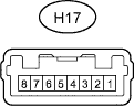
Tester Connection Wiring Color Terminal Description Condition Specified Condition H17-1 (E) - Body ground W-B - Body ground Ground Always Below 1 Ω H17-3 (IG) - Body ground L - Body ground Power supply (IG) Ignition switch ON 11 to 14 V H17-2 (D) - Body ground B - Body ground Defogger signal Ignition switch ON, defogger switch off 11 to 14 V H17-2 (D) - Body ground B - Body ground Defogger signal Ignition switch ON, defogger switch on Below 1 V
-