POWER WINDOW CONTROL SYSTEM Driver Side Power Window Motor Circuit
DESCRIPTION
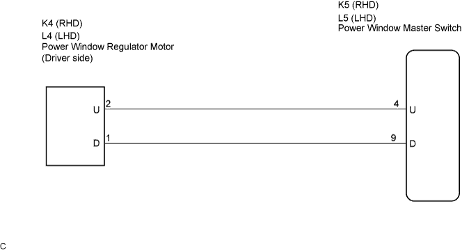
This circuit transmits signals from the power window master switch to the power window regulator motor (Driver side).
WIRING DIAGRAM
INSPECTION PROCEDURE
PROCEDURE
-
INSPECT POWER WINDOW REGULATOR MOTOR
-
Remove the power window motor.
-
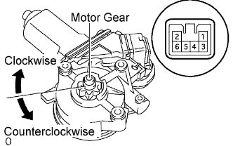
Apply battery voltage to the motor connector according to the table below.
Note
Do not apply battery to any terminals except terminals 1 and 2.
Standard Measurement Condition Specified Condition Battery positive (+) → Terminal 1 (D)
Battery negative (-) → Terminal 2 (U)
Motor gear rotates clockwise Battery positive (+) → Terminal 2 (U)
Battery negative (-) → Terminal 1 (D)
Motor gear rotates counterclockwise
NG 
REPLACE POWER WINDOW REGULATOR MOTOR
OK 
-
-
CHECK WIRE HARNESS (WINDOW REGULATOR MOTOR - POWER WINDOW MASTER SWITCH)
-
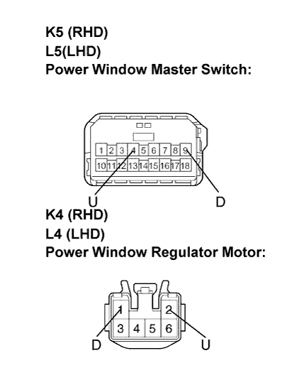
Disconnect the K5 (L5) and K4 (L4) connectors.
-
Measure the resistance according to the value(s) in the table below.
Standard resistance LHD Models Tester Connection Condition Specified Condition L5-4 (U) - L4-2(U) Always Below 1 Ω L5-9 (D) - L4-1 (D) Always Below 1 Ω L5-4 (U) - Body ground Always 10 kΩ or higher L5-9 (D) - Body ground Always 10 kΩ or higher RHD Models Tester Connection Condition Specified Condition K5-4 (U) - K4-2(U) Always Below 1 Ω K5-9 (D) - K4-1 (D) Always Below 1 Ω K5-4 (U) - Body ground Always 10 kΩ or higher K5-9 (D) - Body ground Always 10 kΩ or higher
NG
REPAIR OR REPLACE HARNESS OR CONNECTOR
OK 
PROCEED TO NEXT INSPECTION SHOWN IN PROBLEM SYMPTOMS TABLE
-