POWER WINDOW CONTROL SYSTEM Power Window Master Switch Power Source Circuit
DESCRIPTION
This circuit supplies power to operate the power window master switch.
WIRING DIAGRAM
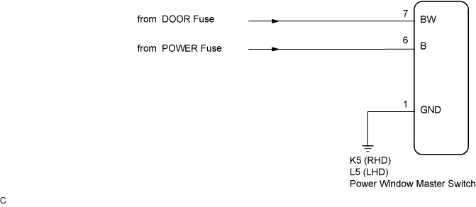
INSPECTION PROCEDURE
PROCEDURE
-
CHECK WIRE HARNESS (POWER WINDOW MASTER SWITCH - BATTERY AND BODY GROUND)
-
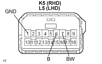
Disconnect the K5 (L5) connector.
-
Measure the voltage and resistance according to the value(s) in the table below.
Standard voltage LHD Models Tester Connection Condition Specified Condition L5-6 (B) - Body ground Always 10 to 14 V L5-7 (BW) - Body ground Ignition switch ON 10 to 14 V RHD Models Tester Connection Condition Specified Condition K5-6 (B) - Body ground Always 10 to 14 V K5-7 (BW) - Body ground Ignition switch ON 10 to 14 V Standard resistance LHD Models Tester Connection Condition Specified Condition L5-1 (GND) - Body ground Always Below 1 Ω RHD Models Tester Connection Condition Specified Condition K5-1 (GND) - Body ground Always Below 1 Ω
NG 
REPAIR OR REPLACE HARNESS OR CONNECTOR
OK 
PROCEED TO NEXT CIRCUIT INSPECTION IN PROBLEM SYMPTOMS TABLE
-