POWER WINDOW CONTROL SYSTEM TERMINALS OF ECU
-
POWER WINDOW MASTER SWITCH

-
Disconnect the K5 (L5) switch with the K5 (L5) switch connector still connected.
-
Measure the voltage according to the value(s) in the table below.
Symbols (Terminal No.) Wiring Color Terminal Description Condition Specified Condition VCC (3) - SGND (2) W - BR Power supply Ignition switch ON, power window master switch OFF → UP (Manual/Auto) or OFF → DOWN (Manual/Auto) Below 1 V → 10 to 14 V U (4) - GND (1) Y - W-B Power window motor UP output Ignition switch ON, power window master switch OFF → UP (Manual/Auto) Below 1 V → 10 to 14 V B (6) - GND (1) L - W-B +B (B) power supply Ignition switch ON 10 to 14 V BW (7) - GND (1) R - W-B +B (BW) power supply Constant 10 to 14 V D (9) - GND (1) G - W-B Power window motor DOWN output Ignition switch ON, power window master switch OFF → DOWN (Manual/Auto) Below 1 V → 10 to 14 V DCTY (11) - GND (1) R - W-B Door courtesy switch signal Driver side door OPEN → CLOSE 10 to 14 V → Below 1 V U (13) - GND (1) L - W-B Power window motor UP output (Remote) Ignition switch ON, power window master switch OFF → UP (Remote) Below 1 V → 10 to 14 V PLS (14) - SGND (2) L - BR Power window motor sensor signal Power window operating Pulse generation D (15) - GND (1) R-L - W-B*1
R - W-B*2
Power window motor DOWN output (Remote) Ignition switch ON, power window master switch OFF → DOWN (Remote) Below 1 V → 10 to 14 V PLS2 (17) - SGND (2) Y - BR Power window motor sensor signal Power window operating Pulse generation
-
*1: for LHD
-
*2: for RHD
-
-
Disconnect the K5 (L5) switch connector.
-
Measure the voltage according to the value(s) in the table below.
Symbols (Terminal No.) Wiring Color Terminal Description Condition Specified Condition GND (1) - Body ground W-B - Body ground Ground Constant Below 1 Ω
-
-
POWER WINDOW SWITCH

-
Disconnect the L6 (K6) switch with the L6 (K6) switch connector still connected.
-
Measure the voltage according to the value(s) in the table below.
Symbols (Terminal No.) Wiring Color Terminal Description Condition Specified Condition D (1) - Body ground G - Body ground Power window motor DOWN output Ignition switch ON, power window switch OFF → DOWN Below 1 V → 10 to 14 V SD (2) - Body ground R-L - Body ground*1
R - Body ground*2
Power window motor DOWN output (Remote) Ignition switch ON, power window master switch OFF → DOWN (Remote) Below 1 V → 10 to 14 V U (3) - Body ground Y - Body ground Power window motor UP output Ignition switch ON, power window switch OFF → UP Below 1 V → 10 to 14 V B (4) - Body ground L - Body ground +B (B) power supply Ignition switch ON 10 to 14 V SU (5) - Body ground L - Body ground Power window motor UP output (Remote) Ignition switch ON, power window master switch OFF → UP (Remote) Below 1 V → 10 to 14 V
-
*1: for LHD
-
*2: for RHD
-
-
-
INSTRUMENT PANEL JUNCTION BLOCK
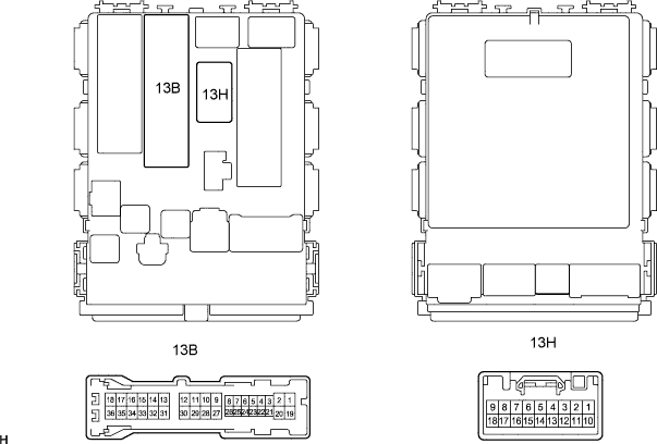
Symbols (Terminal No.) Wiring Color Terminal Description Condition Specified Condition B (13B-36) - Body ground W-L - Body ground +B (B) power supply Ignition switch ON 10 to 14 V BW (13H-1) - Body ground W-R - Body ground +B (BW) power supply Always 10 to 14 V