METER / GAUGE SYSTEM, Diagnostic DTC:B1507, B1508
| DTC Code | DTC Name |
|---|---|
| B1507 | Open in Turn Signal Circuit |
| B1508 | Short in Turn Signal / Hazard Flasher Circuit |
DESCRIPTION
These DTCs are stored when the combination meter assembly detects an open in a turn signal light circuit, a short in a turn signal light circuit, or a short in the hazard warning light circuit.
| DTC Code | DTC Detection Condition | Trouble Area |
|---|---|---|
| B1507 | When IG voltage is 9.5 V or more and the following condition is detected:
|
|
| B1508 | When IG voltage is 9.5 V or more and the following condition is detected:
|
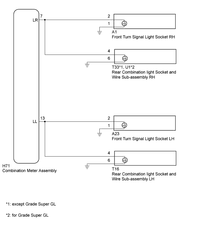
WIRING DIAGRAM
INSPECTION PROCEDURE
Note
Inspect the bulbs for circuits related to this system before performing the following inspection procedure.
PROCEDURE
-
CHECK FOR DTC
-
Clear the DTCs Click here.
-
Check for DTCs Click here.
OK DTC B1507 or B1508 output does not occur.
NG 
CHECK HARNESS AND CONNECTOR (COMBINATION METER - FRONT TURN SIGNAL LIGHT SOCKET LH, REAR COMBINATION LIGHT SOCKET AND WIRE LH AND BODY GROUND) Click here
OK 
USE SIMULATION METHOD TO CHECK Click here
-
-
CHECK HARNESS AND CONNECTOR (COMBINATION METER - FRONT TURN SIGNAL LIGHT SOCKET LH, REAR COMBINATION LIGHT SOCKET AND WIRE LH AND BODY GROUND)
-
Disconnect the H71 combination meter assembly connector.
-
Disconnect the A23 front turn signal light socket assembly LH connector
-
Disconnect the T16 rear combination light socket and wire sub-assembly LH connector.
-
Measure the resistance according to the value(s) in the table below.
Standard Resistance Tester Connection Condition Specified Condition H71-13 (LL) - A23-2 Always Below 1 Ω H71-13 (LL) - T16-4 Always Below 1 Ω A23-1 - Body ground Always Below 1 Ω T16-6 - Body ground Always Below 1 Ω H71-13 (LL) or A23-2 - Body ground Always 10 kΩ or higher H71-13 (LL) or T16-4 - Body ground Always 10 kΩ or higher
NG 
REPAIR OR REPLACE HARNESS OR CONNECTOR
OK 
-
-
CHECK HARNESS AND CONNECTOR (COMBINATION METER - FRONT TURN SIGNAL LIGHT SOCKET RH, REAR COMBINATION LIGHT SOCKET AND WIRE RH AND BODY GROUND)
-
Disconnect the H71 combination meter assembly connector.
-
Disconnect the A1 front turn signal light socket assembly RH connector
-
Disconnect the T33*1 or U1*2 rear combination light socket and wire sub-assembly LH connector.
-
*1: except Grade Super GL
-
*2: for Grade Super GL
-
-
Measure the resistance according to the value(s) in the table below.
Standard Resistance except Grade Super GL Tester Connection Condition Specified Condition H71-7 (LR) - A1-2 Always Below 1 Ω H71-7 (LR) - T33-4 Always Below 1 Ω A1-1 - Body ground Always Below 1 Ω T33-6 - Body ground Always Below 1 Ω H71-7 (LR) or A1-2 - Body ground Always 10 kΩ or higher H71-7 (LR) or T33-4 - Body ground Always 10 kΩ or higher for Grade Super GL Tester Connection Condition Specified Condition H71-7 (LR) - A1-2 Always Below 1 Ω H71-7 (LR) - U1-4 Always Below 1 Ω A1-1 - Body ground Always Below 1 Ω U1-6 - Body ground Always Below 1 Ω H71-7 (LR) or A1-2 - Body ground Always 10 kΩ or higher H71-7 (LR) or U1-4 - Body ground Always 10 kΩ or higher
NG
REPAIR OR REPLACE HARNESS OR CONNECTOR
OK
-
-
CHECK FRONT TURN SIGNAL LIGHT SOCKET
-
Temporarily replace the front turn signal light socket with a new or normally functioning one.
-
for LED Headlight: Click here
-
for Halogen Headlight: Click here
-
-
Clear the DTCs Click here.
-
Check for DTCs Click here.
OK No DTCs are output.
NG
CHECK REAR COMBINATION LIGHT SOCKET AND WIRE SUB-ASSEMBLY Click here
OK
END (FRONT TURN SIGNAL LIGHT SOCKET IS DEFECTIVE)
-
-
CHECK REAR COMBINATION LIGHT SOCKET AND WIRE SUB-ASSEMBLY
-
Temporarily replace the rear combination light socket and wire sub-assembly with a new or normally functioning one Click here
-
Clear the DTCs Click here.
-
Check for DTCs Click here.
OK No DTCs are output.
NG
REPLACE COMBINATION METER ASSEMBLY Click here
OK
END (REAR COMBINATION LIGHT SOCKET AND WIRE SUB-ASSEMBLY IS DEFECTIVE)
-