SLIDE DOOR LOCK INSPECTION
-
INSPECT POWER SLIDE DOOR LOCK ASSEMBLY RH
-
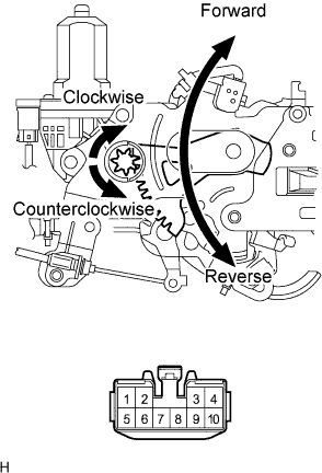
Inspect the door closer motor.
-
Apply battery voltage and check operation of the slide door closer motor.
Standard Measurement Condition Specified Condition Battery positive (+) → Terminal 2
Battery negative (-) → Terminal 1
Close (Forward) Battery positive (+) → Terminal 1
Battery negative (-) → Terminal 2
Open (Reverse)
-
-
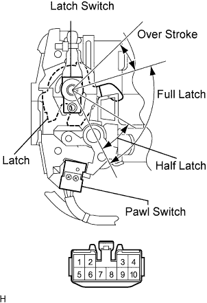
Inspect the pawl switch and latch switch
-
Measure the resistance when the switch is operated according to the value(s) in the table below.
Standard resistance Pawl switch Tester Connection Condition Specified Condition 8 - 9
-
Open
-
Half latch
-
Full latch
10 kΩ or higher 8 - 9 Unlatched Below 1 Ω Latch switch Tester Connection Condition Specified Condition 3 - 4, 4- 8 Open Below 1 Ω 4 - 8 Half latch Below 1 Ω 3 - 4, 4- 8 Full latch 10 kΩ or higher - Over stroke 10 kΩ or higher -
-
-
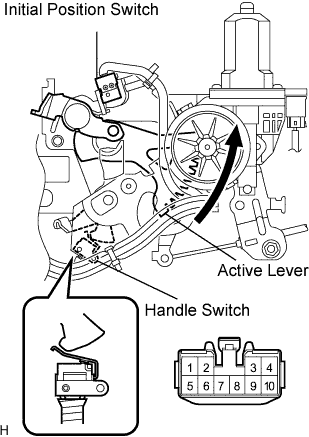
Inspect the initial position switch and handle switch.
-
Measure the resistance when the switch is operated according to the value(s) in the table below.
Standard resistance Tester Connection Condition Specified Condition 8 - 10
-
Handle switch ON (Handle initial position)
-
Initial position switch OFF (Active lever initial position)
10 kΩ or higher 8 - 10
-
Handle switch OFF (As handling)
-
Initial position switch OFF (Active lever initial position)
10 kΩ or higher 8 - 10
-
Handle switch ON (Handle initial position)
-
Initial position switch ON (As closer operating)
Below 1 Ω 8 - 10
-
Handle switch OFF (As handling)
-
Initial position switch ON (As closer operating)
10 kΩ or higher -
-
-
-
INSPECT POWER SLIDE DOOR LOCK ASSEMBLY LH
-
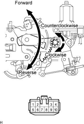
Inspect the door closer motor.
-
Apply battery voltage and check operation of the slide door closer motor.
Standard Measurement Condition Specified Condition Battery positive (+) → Terminal 2
Battery negative (-) → Terminal 1
Close (Forward) Battery positive (+) → Terminal 1
Battery negative (-) → Terminal 2
Open (Reverse)
-
-
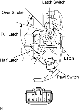
Inspect the pawl switch and latch switch
-
Measure the resistance when the switch is operated according to the value(s) in the table below.
Standard resistance Pawl switch Tester Connection Condition Specified Condition 8 - 9
-
Open
-
Half latch
-
Full latch
10 kΩ or higher 8 - 9 Unlatched Below 1 Ω Latch switch Tester Connection Condition Specified Condition 3 - 4, 4- 8 Open Below 1 Ω 4 - 8 Half latch Below 1 Ω 3 - 4, 4- 8 Full latch 10 kΩ or higher - Over stroke 10 kΩ or higher -
-
-
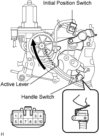
Inspect the initial position switch and handle switch.
-
Measure the resistance when the switch is operated according to the value(s) in the table below.
Standard resistance Tester Connection Condition Specified Condition 8 - 10
-
Handle switch ON (Handle initial position)
-
Initial position switch OFF (Active lever initial position)
10 kΩ or higher 8 - 10
-
Handle switch OFF (As handling)
-
Initial position switch OFF (Active lever initial position)
10 kΩ or higher 8 - 10
-
Handle switch ON (Handle initial position)
-
Initial position switch ON (As closer operating)
Below 1 Ω 8 - 10
-
Handle switch OFF (As handling)
-
Initial position switch ON (As closer operating)
10 kΩ or higher -
-
-