SMART ENTRY AND START SYSTEM (for Entry Function) TERMINALS OF ECU
-
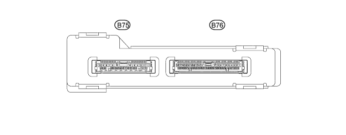
CHECK CERTIFICATION ECU (SMART KEY ECU ASSEMBLY)
-
Disconnect the B75 and B76 certification ECU (smart key ECU assembly) connectors.
-
Measure the voltage and resistance according to the value(s) in the table below.
Tech Tips
Measure the values on the wire harness side with the connector disconnected.
Tester Connection Input/Output Wiring Color Terminal Description Condition Specified Condition Related Data List Item B75-10 (E) - Body ground - W-B - Body ground Ground Always Below 1 Ω - B75-1 (+B) - B75-10 (E) Input L - W-B +B power supply Always 11 to 14 V - -
Connect the B75 and B76 certification ECU (smart key ECU assembly) connectors.
-
Measure the voltage and check for pulses according to the value(s) in the table below.
Tester Connection Input/Output Wiring Color Terminal Description Condition Specified Condition Related Data List Item B75-21 (ACCD) - B75-10 (E) Output R - W-B ACC signal Engine switch off → Engine switch on (ACC) 1 V or less → 8.5 V or higher - B75-20 (IG1D) - B75-10 (E) Output B - W-B IG1 signal Engine switch on (ACC) → Engine switch on (IG) 1 V or less → 9 V or higher - B76-31 (CLG1) - B75-10 (E) Input/Output G - W-B Output to No. 1 indoor electrical key antenna assembly (front bumper RH) (request signal [challenge] is sent to No. 1 indoor electrical key antenna assembly [front bumper RH] from certification ECU [smart key ECU assembly] to form detection area) Procedure:
-
Engine switch off
-
All doors closed
Not pulse generation Overhead + Driver Side (key diagnostic mode) Procedure:
-
Engine switch off
-
All doors closed
-
While carrying the electrical key transmitter sub-assembly, press the trigger switch on the front door outside handle assembly RH.
Pulse generation (See waveform 1) B76-30 (CG1B) - B75-10 (E) Input/Output R - W-B Output to No. 1 indoor electrical key antenna assembly (front bumper RH) (terminal on opposite side of component from CLG1 output terminal) Procedure:
-
Engine switch off
-
All doors closed
Not pulse generation Overhead + Driver Side (key diagnostic mode) Procedure:
-
Engine switch off
-
All doors closed
-
While carrying the electrical key transmitter sub-assembly, press the trigger switch on the front door outside handle assembly RH.
Pulse generation (See waveform 1) B76-6 (CLG2) - B75-10 (E) Input/Output G - W-B Output to No. 1 indoor electrical key antenna assembly (front bumper LH) (request signal [challenge] is sent to No. 1 indoor electrical key antenna assembly [front bumper LH] from certification ECU [smart key ECU assembly] to form detection area) Procedure:
-
Engine switch off
-
All doors closed
Not pulse generation Overhead + Passenger Side (key diagnostic mode) Procedure:
-
Engine switch off
-
All doors closed
-
While carrying the electrical key transmitter sub-assembly, press the trigger switch on the front door outside handle assembly LH.
Pulse generation (See waveform 2) B76-23 (CG2B) - B75-10 (E) Input/Output R - W-B Output to No. 1 indoor electrical key antenna assembly (front bumper LH) (terminal on opposite side of component from CLG2 output terminal) Procedure:
-
Engine switch off
-
All doors closed
Not pulse generation Overhead + Passenger Side (key diagnostic mode) Procedure:
-
Engine switch off
-
All doors closed
-
While carrying the electrical key transmitter sub-assembly, press the trigger switch on the front door outside handle assembly LH.
Pulse generation (See waveform 2) B75-4 (TSW1) - B75-10 (E) Input BR - W-B Driver door trigger switch signal input sends signals from trigger switch on front door outside handle assembly RH to certification ECU (smart key ECU assembly).
Certification ECU (smart key ECU assembly) sends 12 V pulse waveform every 20 ms. from terminal TSW. When trigger switch is pressed, the pulse is grounded.
Procedure:
-
Engine switch off
-
All doors closed
-
Driver door trigger switch not pressed → pressed
9.5 to 16 V → Below 1.5 V D-Door Trigger Switch B75-12 (TSW2) - B75-10 (E) Input B - W-B Passenger door trigger switch signal input sends signals from trigger switch on front door outside handle assembly LH to certification ECU (smart key ECU assembly).
Certification ECU (smart key ECU assembly) sends 12 V pulse waveform every 20 ms. from terminal TSW. When trigger switch is pressed, the pulse is grounded.
Procedure:
-
Engine switch off
-
All doors closed
-
Passenger door trigger switch not pressed → pressed
9.5 to 16 V → Below 1.5 V P-Door Trigger Switch B75-14 (TSW5) - B75-10 (E) Input V - W-B Back door trigger switch signal input sends signals from trigger switch on license plate light assembly to certification ECU (smart key ECU assembly).
Certification ECU (smart key ECU assembly) sends 12 V pulse waveform every 20 ms. from terminal TSW. When trigger switch is pressed, the pulse is grounded.
Procedure:
-
Engine switch off
-
All doors closed
-
Back door trigger switch not pressed → pressed
4.5 V or higher → Below 1.5 V Tr/B-Door Unlock SW B76-28 (CGND) - B75-10 (E) Output GR - W-B Output to No. 2 indoor electrical key antenna assembly (front floor) Procedure:
-
All doors closed
-
Engine switch off
-
Electrical key transmitter sub-assembly not inside vehicle
-
Door is open
-
Door is closed
-
Within 30 seconds
Pulse generation (See waveform 3) Overhead + front room (key diagnostic mode) B76-27 (CG6B) - B75-10 (E) Input/Output BR - W-B Output to No. 2 indoor electrical key antenna assembly (front floor) (terminal on opposite side of component from CGND output terminal) Procedure:
-
All doors closed
-
Engine switch off
-
Electrical key transmitter sub-assembly not inside vehicle
-
Door is open
-
Door is closed
-
Within 30 seconds
Pulse generation (See waveform 3) Overhead + front room (key diagnostic mode) B76-26 (CLG6) - B75-10 (E) Input/Output G - W-B Output to No. 3 indoor electrical key antenna assembly (rear floor) Procedure:
-
All doors closed
-
Engine switch off
-
Electrical key transmitter sub-assembly not inside vehicle
-
Door is open
-
Door is closed
-
Within 30 seconds
Pulse generation (See waveform 3) Overhead + room (key diagnostic mode) B76-9 (BGND) - B75-10 (E) Output R - W-B Output to No. 3 indoor electrical key antenna assembly (rear floor) (terminal on opposite side of component from CLG6 output terminal) Procedure:
-
All doors closed
-
Engine switch off
-
Electrical key transmitter sub-assembly not inside vehicle
-
Door is open
-
Door is closed
-
Within 30 seconds
Pulse generation (See waveform 3) Overhead + room (key diagnostic mode) B76-8 (CLG8) - B75-10 (E) Input/Output BR - W-B Output to electrical key antenna (back door) Procedure:
-
Engine switch off
-
All doors closed
Not pulse generation Overhead + Luggage (key diagnostic mode) Procedure:
-
Engine switch off
-
All doors closed
-
Back door trigger switch off → on
Pulse generation (See waveform 4) B76-24 (CG8B) - B75-10 (E) Input/Output GR - W-B Output to electrical key antenna (back door) (terminal on opposite side of component from CLG8 output terminal) Procedure:
-
Engine switch off
-
All doors closed
Not pulse generation Overhead + Luggage (key diagnostic mode) Procedure:
-
Engine switch off
-
All doors closed
-
Back door trigger switch off → on
Pulse generation (See waveform 4) B75-9 (LSWP) - B75-10 (E) Input Y - W-B Except front door RH unlock detection switch input Procedure:
-
Engine switch off
-
All doors locked
-
Lock button of electrical key transmitter sub-assembly not pressed
Below 1 V - Procedure:
-
Engine switch off
-
All doors locked
-
Lock button of electrical key transmitter sub-assembly pressed
8.5 V or higher B76-13 (RDA3) - B75-10 (E) Output W - W-B Signal output to instrument panel junction block assembly (body computer) Procedure:
-
Engine switch off
-
All doors locked
-
10 seconds elapsed after all doors locked
-
Electrical key transmitter sub-assembly unlock switch not pressed
11 to 14 V - Procedure:
-
Engine switch off
-
All doors locked
-
10 seconds elapsed after all doors locked
-
Electrical key transmitter sub-assembly unlock switch pressed
Pulse generation B76-36 (PRG3) - B75-10 (E) Input B - W-B Signal input from instrument panel junction block assembly (body computer) Procedure:
-
Engine switch off
-
All doors locked
-
10 seconds elapsed after all doors locked
-
Electrical key transmitter sub-assembly unlock switch not pressed
11 to 14 V - Procedure:
-
Engine switch off
-
All doors locked
-
10 seconds elapsed after all doors locked
-
Electrical key transmitter sub-assembly unlock switch pressed
Pulse generation -
-
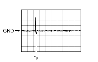
Text in Illustration *a Trigger switch ON Using an oscilloscope, check waveform 1.
Tech Tips
The oscilloscope waveform shown in the illustration is an example for reference only. Noise, chattering, etc. are not shown.
Waveform 1 (Reference) Item Content Tester Connection
-
B76-31 (CLG1) - B75-10 (E)
-
B76-30 (CG1B) - B75-10 (E)
Tool Setting 2 V/DIV., 500 ms./DIV. Condition Procedure:
-
Engine switch off
-
All doors closed
-
While carrying the electrical key transmitter sub-assembly, press the trigger switch on the front door outside handle assembly RH.
-
-
Text in Illustration *a Trigger switch ON Using an oscilloscope, check waveform 2.
Tech Tips
The oscilloscope waveform shown in the illustration is an example for reference only. Noise, chattering, etc. are not shown.
Waveform 2 (Reference) Item Content Tester Connection
-
B76-6 (CLG2) - B75-10 (E)
-
B76-23 (CG2B) - B75-10 (E)
Tool Setting 2 V/DIV., 500 ms./DIV. Condition Procedure:
-
Engine switch off
-
All doors closed
-
While carrying the electrical key transmitter sub-assembly, press the trigger switch on the front door outside handle assembly LH.
-
-
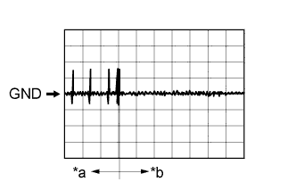
Text in Illustration *a Door open *b After approximately 30 seconds from when the door is closed Using an oscilloscope, check waveform 3.
Tech Tips
The oscilloscope waveform shown in the illustration is an example for reference only. Noise, chattering, etc. are not shown.
Waveform 3 (Reference) Item Content Tester Connection
-
B76-26 (CLG6) - B75-10 (E)
-
B76-27 (CG6B) - B75-10 (E)
-
B76-28 (CGND) - B75-10 (E)
-
B76-9 (BGND) - B75-10 (E)
Tool Setting 2 V/DIV., 500 ms/DIV. Condition Procedure:
-
All doors closed
-
Engine switch off
-
Electrical key transmitter sub-assembly not inside vehicle
-
Door is open
-
Door is closed
-
Within 30 seconds
-
-
Text in Illustration *a Trigger switch ON Using an oscilloscope, check waveform 4.
Tech Tips
The oscilloscope waveform shown in the illustration is an example for reference only. Noise, chattering, etc. are not shown.
Waveform 4 (Reference) Item Content Tester Connection
-
B76-8 (CLG8) - B75-10 (E)
-
B76-24 (CG8B) - B75-10 (E)
Tool Setting 2 V/DIV., 500 ms/DIV. Condition Procedure:
-
Engine switch off
-
All doors closed
-
Back door trigger switch off → on
-
-
-
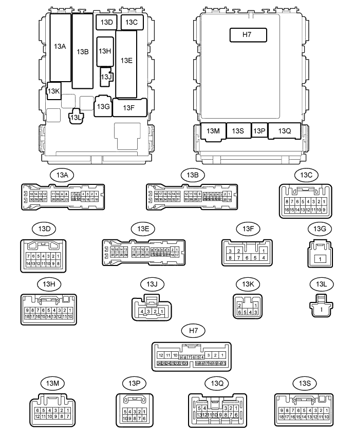
CHECK INSTRUMENT PANEL JUNCTION BLOCK ASSEMBLY (BODY COMPUTER)
-
Disconnect the 13M, 13G, 13C and H7 instrument panel junction block assembly (body computer) connectors.
-
Measure the voltage and resistance according to the value(s) in the table below.
Tech Tips
Measure the values on the wire harness side with the connector disconnected.
Tester Connection Input/Output Wiring Color Terminal Description Condition Specified Condition 13M-7 (GND) - Body ground - W-B - Body ground Ground Always Below 1 Ω 13G-1 (BECU) - Body ground Input BG - Body ground Battery power supply (for CPU) Always 11 to 14 V 13C-4 (IG) - Body ground Input B - Body ground Engine switch power supply Engine switch on (IG) 11 to 14 V H7-4 (LSWD) - Body ground Input W - Body ground Driver door lock position switch input Front door RH lock→ unlock 10 kΩ or higher → Below 1 Ω -
Reconnect the instrument panel junction block assembly (body computer) connectors.
-
Measure the voltage and check for pulses according to the value(s) in the table below.
Tester Connection Input/Output Wiring Color Terminal Description Condition Specified Condition 13E-11 (DCTY) - Body ground Input G - Body ground Front door courtesy light switch RH input Driver side door closed → Open 11 to 14 V* → Below 1 V
Pulse generation* → Below 1 V
13E-10 (PCTY) - Body ground Input R - Body ground Front door courtesy light switch LH input Front passenger side door closed → Open 11 to 14 V* → Below 1 V
Pulse generation* → Below 1 V
13A-30 (RRCY) - Body ground Input W - Body ground Rear door courtesy light switch LH input Rear door LH door closed → Open 11 to 14 V* → Below 1 V
Pulse generation* → Below 1 V
13A-18 (RRCY) - Body ground Input W - Body ground Rear door courtesy light switch RH input Rear door RH door closed → Open 11 to 14 V* → Below 1 V
Pulse generation* → Below 1 V
13A-24 (RRCY) - Body ground Input W - Body ground Back door courtesy light switch input Back door closed → Open 11 to 14 V* → Below 1 V
Pulse generation* → Below 1 V
13B-17 (ACT+) - Body ground Output L - Body ground Door lock motor lock drive output Door lock control switch off → On (lock) Below 1 V → 11 to 14 V → Below 1 V 13B-35 (ACT-) - Body ground Output L - Body ground Door lock motor unlock drive output Door lock control switch off → On (unlock) Below 1 V → 11 to 14 V → Below 1 V H7-6 (HAZ) - Body ground Input W - Body ground Hazard signal output Door lock answer back operation 11 to 14 V → Below 1 V H7-7 (RDA) - Body ground Input W - Body ground Signal input from certification ECU (smart key ECU assembly) Procedure:
-
Engine switch off
-
All doors locked
-
10 seconds elapsed after all doors locked
-
Electrical key transmitter sub-assembly unlock switch not pressed
11 to 14 V Procedure:
-
Engine switch off
-
All doors locked
-
10 seconds elapsed after all doors locked
-
Electrical key transmitter sub-assembly unlock switch pressed
Pulse generation H7-8 (PRG) - Body ground Output B - Body ground Signal output to certification ECU (smart key ECU assembly) Procedure:
-
Engine switch off
-
All doors locked
-
10 seconds elapsed after all doors locked
-
Electrical key transmitter sub-assembly unlock switch not pressed
11 to 14 V Procedure:
-
Engine switch off
-
All doors locked
-
10 seconds elapsed after all doors locked
-
Electrical key transmitter sub-assembly unlock switch pressed
Pulse generation
-
*: The specified value changes depending on vehicle conditions.
-
-