WIPER SWITCH REMOVAL
-
DISCONNECT CABLE FROM NEGATIVE BATTERY TERMINAL
Note
After turning the ignition switch off, waiting time may be required before disconnecting the cable from the battery terminal. Therefore, make sure to read the disconnecting the cable from the battery terminal notice before proceeding with work Click here.
-
REMOVE INSTRUMENT CLUSTER FINISH PANEL GARNISH NO. 1
-
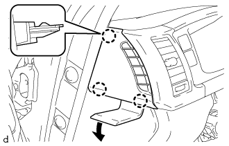
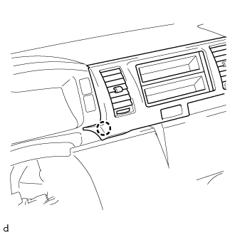
Using a moulding remover D, detach the 3 claws and remove the instrument cluster finish panel garnish No. 1.
-
-
REMOVE INSTRUMENT CLUSTER FINISH PANEL GARNISH NO. 2
-
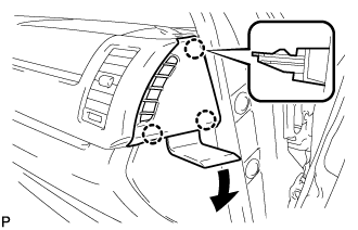
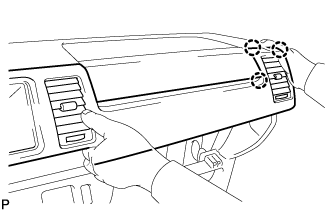
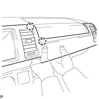
Using a moulding remover D, detach the 3 claws and remove the instrument cluster finish panel garnish No. 2.
-
-
REMOVE INSTRUMENT CLUSTER FINISH PANEL SUB-ASSEMBLY CENTER
-
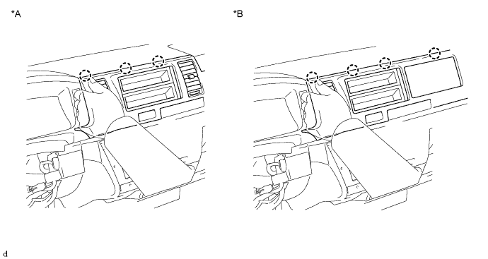
for Standard Body:
Using a moulding remover D, detach the 4 claws in the order shown in the illustration.
-
for Wide Body:
Using a moulding remover D, detach the 5 claws in the order shown in the illustration.
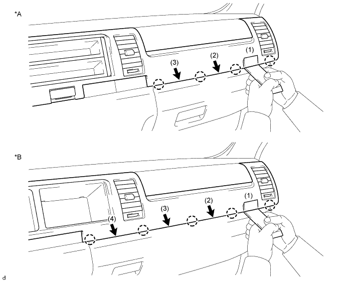
Text in Illustration *A for Standard Body *B for Wide Body -
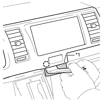
Text in Illustration *1 Protective Tape Apply protective tape as shown in the illustration.
-
Using a moulding remover D, detach the claw.
-
Detach the claw as shown in the illustration.
-
Detach the 3 claws as shown in the illustration.
-
Detach the 2 claws as shown in the illustration.
-
for Standard Body:
Detach the 3 claws and remove the instrument cluster finish panel sub-assembly center.
-
for Wide Body:
Detach the 4 claws and remove the instrument cluster finish panel sub-assembly center.
Text in Illustration *A for Standard Body *B for Wide Body
-
-
REMOVE INSTRUMENT CLUSTER FINISH PANEL ASSEMBLY
-
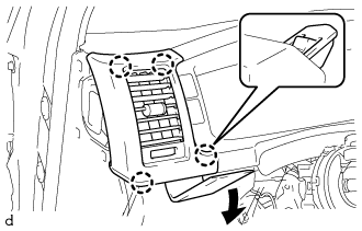
Using a moulding remover D, detach the 4 claws and remove the instrument cluster finish panel assembly.
-
-
REMOVE INSTRUMENT CLUSTER FINISH PANEL SUB-ASSEMBLY
-
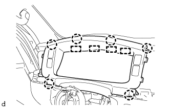
Detach the 6 claws and 4 hooks and remove the instrument cluster finish panel sub-assembly.
-
-
REMOVE COMBINATION METER ASSEMBLY
-
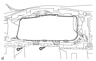
Remove the 2 screws.
-
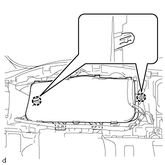
Detach the 2 claws and remove the combination meter assembly.
-
Disconnect the 2 connectors and detach the wire harness clamp.
-
-
REMOVE INSTRUMENT PANEL FINISH PANEL LOWER
-
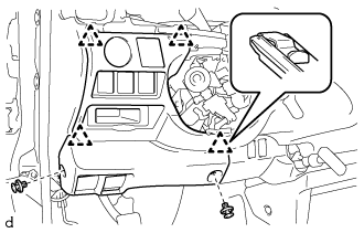
Using a clip remover, remove the 2 clips.
-
Detach the 4 clips and remove the instrument panel finish lower.
-
Disconnect each connector.
-
Push the positions indicated by the arrows in the illustration to disconnect the fuel lid lock control cable and bonnet (hood) control cable assembly from the instrument panel finish lower.
-
-
REMOVE NO. 2 STEERING COLUMN LOWER COVER (w/ Smart Entry and Start System)
-
Detach the 4 claws and remove the No. 2 steering column lower cover.
-
-
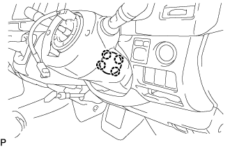
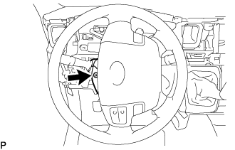
REMOVE STEERING COLUMN LOWER COVER
Tech Tips
Adjust the position of the steering tilt mechanism when performing the procedure.
-
While turning the steering wheel to the right.
-
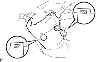
Using a T25 ''TORX'' socket wrench, remove the ''TORX'' screw.
-
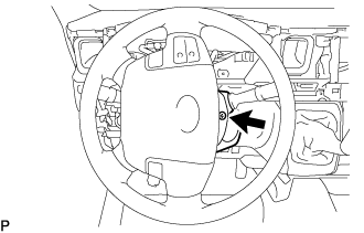
While turning the steering wheel to the left.
-
Using a T25 ''TORX'' socket wrench, remove the ''TORX'' screw.
-
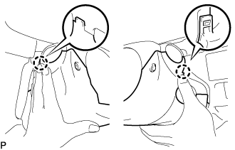
Push the steering column lower cover inward on both sides to detach the 2 claws.
-
Detach the 2 claws and remove the steering column lower cover.
-
-
REMOVE STEERING COLUMN UPPER COVER
-
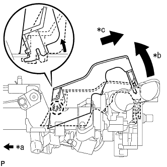
Text in Illustration *a Front of Vehicle *b Raise the backside of the steering column upper cover *c Pull diagonally backwards so that the claw of the steering column upper cover does not break Remove the steering column upper cover from the steering column assembly.
Note
If the steering column upper cover is removed by pulling it directly upwards, the claw may become damaged.
-
-
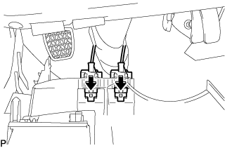
REMOVE WINDSHIELD WIPER SWITCH ASSEMBLY
-
Disconnect the 2 connectors.
-
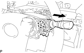
Detach the claw and remove the windshield wiper switch assembly as shown in the illustration.
Note
If the claw is pushed with excessive force, it may be broken.
-