LIGHTING SYSTEM Turn Signal Switch Circuit
DESCRIPTION
The combination meter receives turn signal switch information and controls the turn signal lights.
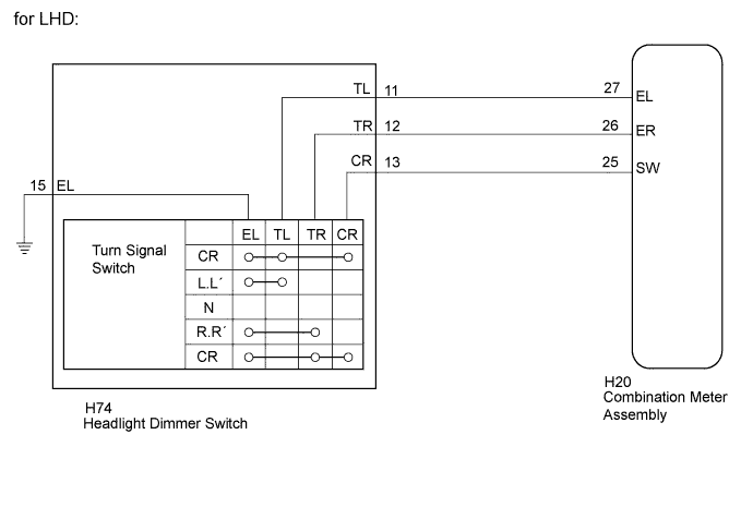
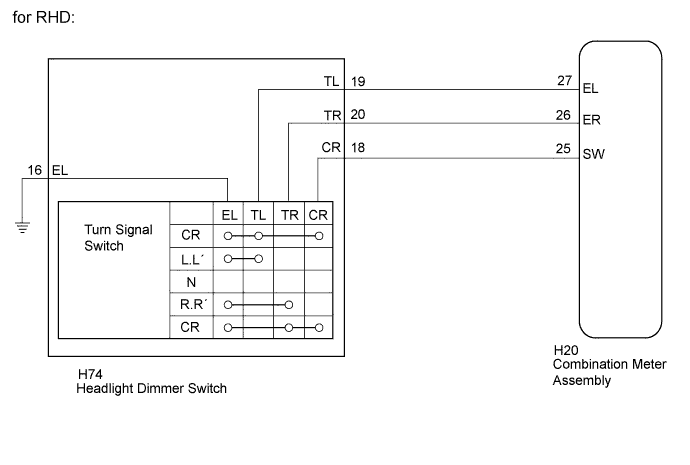
WIRING DIAGRAM
INSPECTION PROCEDURE
PROCEDURE
-
READ VALUE USING GTS (TURN SIGNAL SWITCH)
-
Using the GTS, read the Data List Click here.
Combination Meter Tester Display Measurement Item/Range Normal Condition Diagnostic Note Turn Signal Switch (Right) Turn signal switch (right turn position) signal / ON or OFF ON: Turn signal switch in right turn position
OFF: Turn signal switch not in right turn position
- Turn Signal Switch (Left) Turn signal switch (left turn position) signal / ON or OFF ON: Turn signal switch in left turn position
OFF: Turn signal switch not in left turn position
- OK The display is as specified in the normal condition column.
NG 
INSPECT HEADLIGHT DIMMER SWITCH ASSEMBLY Click here
OK 
REPLACE COMBINATION METER ASSEMBLY Click here
-
-
INSPECT HEADLIGHT DIMMER SWITCH ASSEMBLY
-
Remove the headlight dimmer switch Click here.
-
Inspect the headlight dimmer switch Click here.
NG 
REPLACE HEADLIGHT DIMMER SWITCH ASSEMBLY Click here
OK 
-
-
CHECK HARNESS AND CONNECTOR (HEADLIGHT DIMMER SWITCH - COMBINATION METER)
-
Disconnect the H74 headlight dimmer switch connector.
-
Disconnect the H20 combination meter connector.
-
Measure the resistance according to the value(s) in the table below.
Standard Resistance for LHD Tester Connection Condition Specified Condition H74-11 (TL) - H20-27 (EL) Always Below 1 Ω H74-12 (TR) - H20-26 (ER) H74-13 (CR) - H20-25 (SW) H74-15 (EL) - Body ground H74-11 (TL) - Body ground Always 10 kΩ or higher H74-12 (TR) - Body ground H74-13 (CR) - Body ground for RHD Tester Connection Condition Specified Condition H74-19 (TL) - H20-27 (EL) Always Below 1 Ω H74-20 (TR) - H20-26 (ER) H74-18 (CR) - H20-25 (SW) H74-16 (EL) - Body ground H74-19 (TL) - Body ground Always 10 kΩ or higher H74-20 (TR) - Body ground H74-18 (CR) - Body ground
NG
REPAIR OR REPLACE HARNESS OR CONNECTOR
OK
PROCEED TO NEXT SUSPECTED AREA SHOWN IN PROBLEM SYMPTOMS TABLE Click here
-