CRUISE CONTROL SYSTEM Clutch Switch Circuit
DESCRIPTION
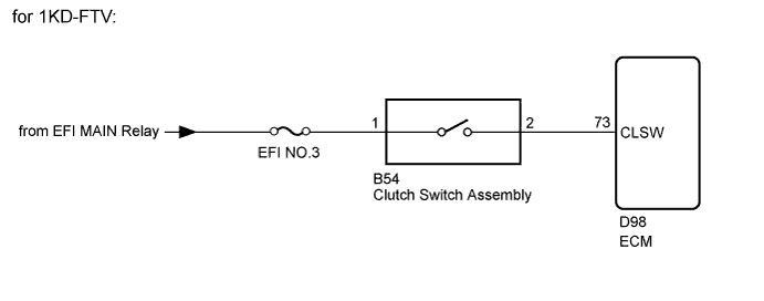
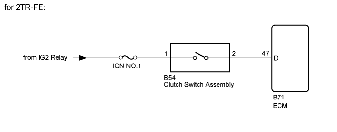
While depressing the clutch pedal, the clutch switch sends a signal to terminal 73 (CLSW)*1 or 47 (D)*2 of the ECM. The ECM cancels cruise control when terminal 73 (CLSW)*1 or 47 (D)*2 receives the signal.
*1: for 1KD-FTV
*2: for 2TR-FE
WIRING DIAGRAM
INSPECTION PROCEDURE
Note
Inspect the fuses for circuits related to this system before performing the following inspection procedure.
PROCEDURE
-
INSPECT CLUTCH SWITCH ASSEMBLY
-
Remove the clutch switch assembly Click here.
-
Inspect the clutch switch assembly Click here.
NG 
REPLACE CLUTCH SWITCH ASSEMBLY Click here
OK 
-
-
CHECK HARNESS AND CONNECTOR (CLUTCH SWITCH ASSEMBLY - ECM AND BATTERY)
-
Disconnect the B54 clutch switch assembly connector.
-
Disconnect the D98*1 or B71*2 ECM connector.
*1: for 1KD-FTV
*2: for 2TR-FE
-
Measure the voltage according to the value(s) in the table below.
Standard Voltage Tester Connection Switch Condition Specified Condition B54-1 - Body ground Ignition switch ON 11 to 14 V Ignition switch off Below 1 V -
Measure the resistance according to the value(s) in the table below.
Standard Resistance for 1KD-FTV Tester Connection Condition Specified Condition B54-2 - D98-73 (CLSW) Always Below 1 Ω B54-2 - Body ground Always 10 kΩ or higher for 2TR-FE Tester Connection Condition Specified Condition B54-2 - B71-47 (D) Always Below 1 Ω B54-2 - Body ground Always 10 kΩ or higher
NG
REPAIR OR REPLACE HARNESS OR CONNECTOR
OK 
PROCEED TO NEXT SUSPECTED AREA SHOWN IN PROBLEM SYMPTOMS TABLE Click here
-