AIR CONDITIONING SYSTEM SYSTEM DESCRIPTION
-
GENERAL
-
Air Conditioning Unit
-
The air conditioner unit has been made compact and lightweight by placing the evaporator and the heater core horizontally, above and below in the unit, and adopting a film type slide door for the air mix door.
-
An RS evaporator (RS: Revolutionary Super Slim), which is thin and lightweight and has excellent cooling performance, is used.
-
An SFA-II heater core (SFA-II: Straight Flow Aluminum-II), which is compact and lightweight and has superior heating performance, is used in the front heater & cooler unit and the rear heater unit.
-
Heater doors that always recirculate some of the inside air even in refresh mode are used for models with the front air conditioner unit to improve the heating performance.
-
The PTC (Positive Temperature Coefficient) heater system contains a PTC heater that heats the air that has passed through the heater core to ensure the proper heater performance.
-
-
Other Equipment
-
The previous air conditioner compressor continues to be used on the diesel engine models, and an external control continuously variable capacity air conditioner compressor is used on the TR engine models.
-
The heater control panel is the rotary switch type. A rotating cable control mechanism is used to make the control unit more compact.
-
-
-
MODEL POSITION AND DAMPER OPERATION
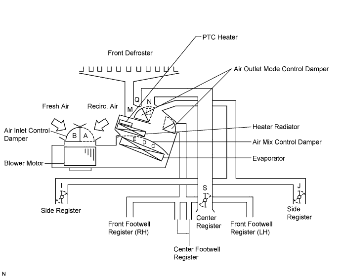
Control Damper Control Position Damper Position Operation Air Inlet Control Damper FRESH B Brings in fresh air. RECIRC A Recirculates internal air. Air Mix Control Film Damper Driver and Front Passenger Side MAX COOL to MAX HOT
(TEMP. SETTING 18 to 32°C (64 to 90°F))
C, D, E Varies the mixture ratio of the fresh air and the recirculation air in order to regulate the temperature continuously from HOT to COOL. Mode Control Film Damper Driver and Front Passenger Side FACE

I, J, M, O, S Air blows out of the front and rear center registers, and side registers. BI - LEVEL

I, J, M, P, S Air mainly blows out of the front and rear center registers, side registers, and footwell register ducts. FOOT

I, J, Q, L, S Air mainly blows out of the front and rear footwell register ducts.
In addition, air blows out slightly from the front and side defrosters, and the side registers.
FOOT / DEF
I, J, N, L, S Air mainly blows out of the front and side defrosters to defrost the windshield. Air also blows out from the front and rear footwell register ducts, and the side registers. DEF

I, J, N, O, S Air blows out of the front and side defrosters and side registers to defrost the windshield. -
AIR OUTLETS AND AIRFLOW VOLUME
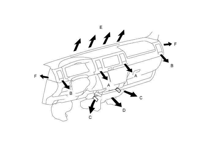
Air Outlet Mode A B C D E F Center Face Side Face Foot Foot Center Defroster Side Defroster FACE


BI-LEVEL


FOOT
FOOT/DEF
DEF
Tech Tips
The size of the circle indicates the proportion of airflow volume. There are 4 sizes.