STEERING GEAR REASSEMBLY

Note
When installing, coat the parts indicated by arrows with power steering fluid, silicon grease and molybdenum disulfide lithium base grease Click here.
-
INSTALL POWER STEERING CYLINDER TUBE OIL SEAL
-
Install the spacer to the power steering rack housing.
Note
Do not damage the inside of the power steering rack housing.
-
Apply power steering fluid to the lip of a new power steering cylinder tube oil seal.
-
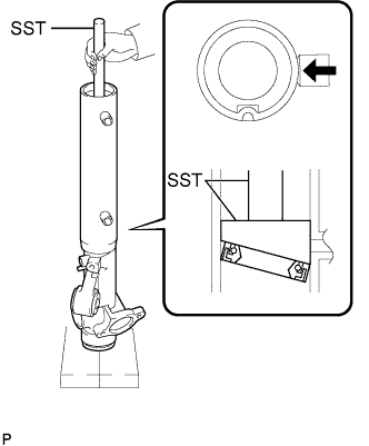
Install the power steering cylinder tube oil seal to the rack housing at a slant.
- SST
- 09950-70010 ( 09951-07360 )
- 09631-00210
Note
-
Ensure the power steering cylinder tube oil seal is installed in the correct direction as shown in the illustration.
-
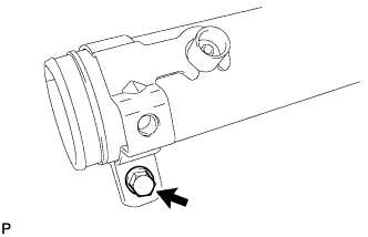
Install the power steering cylinder tube oil seal at an angle of approximately 15° so that the lowermost part comes to the point, indicated by the arrow in the illustration, to prevent damage to the side of the oil seal when it passes the 2 ports.
-
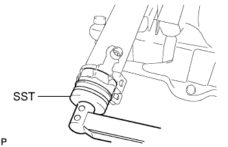
Using SST, insert the power steering cylinder tube oil seal by pushing the SST in by hand until the oil seal passes the 2 ports.
Note
Do not turn the SST when inserting the oil seal.
-
Install SST (09631-00210) to SST (09951-07360) upside down.
- SST
- 09950-70010 ( 09951-07360 )
- 09631-00210
-
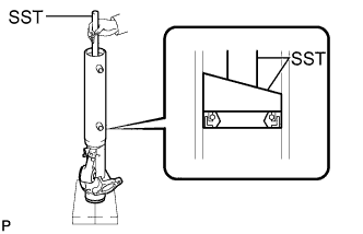
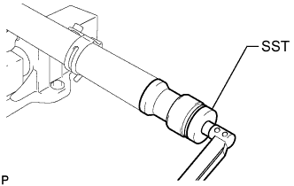
Using SST, level the power steering cylinder tube oil seal by pushing the SST in by hand.
- SST
- 09950-70010 ( 09951-07360 )
- 09631-00210
-
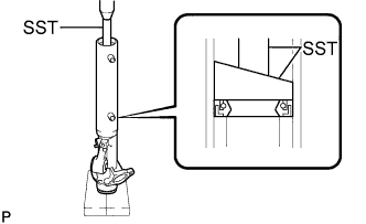
Using SST and a press, install the power steering cylinder tube oil seal.
-
-
INSTALL POWER STEERING RACK
-
Coat a new O-ring with power steering fluid and install it to the power steering rack.
-
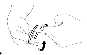
Expand a new oil seal with your fingers.
-
Coat the oil seal with power steering fluid.
-
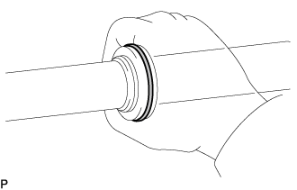
Install the oil seal to the steering rack, and adjust with your fingers.
-
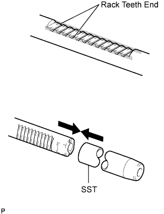
Apply molybdenum disulfide lithium base grease to the rack teeth ends.
Tech Tips
If necessary, scrape the burrs off the rack teeth ends and burnish.
-
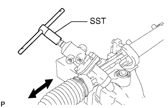
Affix SST to the steering rack.
- SST
- 09631-20111
-
Coat SST with power steering fluid.
-
Install the steering rack to the rack housing.
-
Remove the SST.
-
-
INSTALL CYLINDER END STOPPER
-
Body type narrow:
-
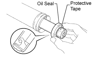
Wrap protective tape around the RH side of the power steering rack and apply power steering fluid.
-
Apply power steering fluid to the lip of a new cylinder end stopper oil seal.
-
Install the cylinder end stopper oil seal to the RH side of the rack housing.
Note
-
Ensure that the cylinder end stopper oil seal is installed in the correct direction as shown in the illustration.
-
Do not damage the cylinder end stopper oil seal.
-
-
Remove the protective tape from the power steering rack.
-
Apply power steering fluid to a new cylinder end stopper O-ring.
-
Install the cylinder end stopper O-ring to the cylinder end stopper.
-
Install a new cylinder end stopper bushing to the cylinder end stopper.
-
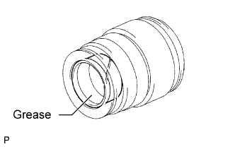
Apply molybdenum disulfide lithium base grease to the entire inner side of the cylinder end stopper.
-
Install the tube support retainer.
-
Using SST, install the cylinder end stopper to the rack housing.
- SST
- 09631-20120
- Torque:
- 78 N*m { 795 kgf*cm, 58 ft.*lbf }
-
Tighten the bolt.
- Torque:
- 19 N*m { 195 kgf*cm, 14 ft.*lbf }
-
-
Body type wide:
-
Wrap protective tape around the RH side of the power steering rack and apply power steering fluid.
-
Apply power steering fluid to the lip of a new cylinder end stopper oil seal.
-
Install the cylinder end stopper oil seal to the RH side of the rack housing.
Note
-
Ensure that the cylinder end stopper oil seal is installed in the correct direction as shown in the illustration.
-
Do not damage the cylinder end stopper oil seal.
-
-
Remove the protective tape from the power steering rack.
-
Install the spacer to the rack housing.
-
Apply power steering fluid to a new cylinder end stopper O-ring.
-
Install the cylinder end stopper O-ring to the cylinder end stopper.
-
Install a new cylinder end stopper bushing to the cylinder end stopper.
-
Apply molybdenum disulfide lithium base grease to the entire inner side of the cylinder end stopper.
-
Using SST, install the cylinder end stopper to the rack housing.
- SST
- 09631-20120
- Torque:
- 78 N*m { 795 kgf*cm, 58 ft.*lbf }
-
-
-
AIR TIGHTNESS TEST
-
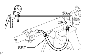
Install SST and a vacuum pump to the rack housing.
- SST
- 09631-12071 ( 09633-00010 )
-
Apply a vacuum of 53 kPa (398 mmHg, 15.65 in.Hg) for approximately 30 seconds.
-
Check that there is no change in the vacuum pressure.
If there is a change in the vacuum pressure, check the installation of the oil seals.
-
-
INSTALL POWER STEERING CONTROL VALVE ASSEMBLY
-
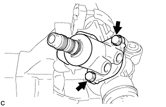
Install the power steering control valve assembly and a new gasket to the rack housing with the 2 bolts.
- Torque:
- 18 N*m { 185 kgf*cm, 13 ft.*lbf }
-
-
INSTALL STEERING RACK GUIDE
-
Install the rack guide seat to the power steering rack guide.
-
Apply molybdenum disulfide lithium base grease to the compression spring and the contact surface of the rack guide seat and the power steering rack.
-
Install the compression spring and the rack guide.
-
Apply sealant to 2 or 3 threads of the rack guide spring cap.
Sealant Toyota Genuine Adhesive 1344, Three Bond 1344 or equivalent -
Using a straight hexagon wrench 24 mm (0.94 in.), install the rack guide spring cap.
-
-
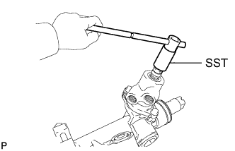
INSPECT TOTAL PRELOAD
-
Using a straight hexagon wrench 24 mm (0.94 in.), tighten the power steering rack guide spring cap.
- Torque:
- 69 N*m { 704 kgf*cm, 51 ft.*lbf }
-
Using a straight hexagon wrench 24 mm (0.94 in.), loosen the power steering rack guide spring cap.
-
Temporarily install the steering rack ends to prevent steering rack over stroke.
Note
Do not fully turn the power steering rack without the steering rack end as it may damage the oil seal in the rack housing and the cylinder end stopper bushing.
-
Using SST, fully turn the power steering rack right and left 10 times to settle.
- SST
- 09616-00011
-
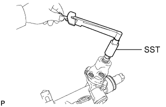
Using a straight hexagon wrench 24 mm (0.94 in.), tighten the power steering rack guide spring cap in small amounts until the preload is within the specified range.
- SST
- 09616-00011
Preload (turning) 0.65 to 1.35 N*m (6.6 to 13.8 kgf*cm, 5.8 to 11.9 in.*lbf) Note
Loosen and tighten the power steering rack guide spring cap again if the preload falls below the specified range.
-
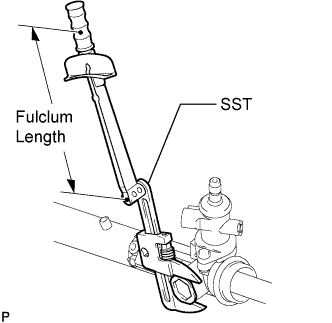
Using SST, install the power steering rack guide spring cap nut.
- SST
- 09922-10010
- Torque:
- 49 N*m { 502 kgf*cm, 36 ft.*lbf }
Note
-
Use SST 09922-10010 following the direction shown in the illustration.
-
Use a torque wrench with a fulcrum length of 345 mm (13.58 in.).
-
Using SST, inspect the total preload.
- SST
- 09616-00011
Preload (turning) 0.65 to 1.35 N*m (6.6 to 13.8 kgf*cm, 5.8 to 11.9 in.*lbf)
-
-
INSTALL RACK END SUB-ASSEMBLY
-
Install 2 new claw washers.
Tech Tips
Align the claws of the claw washer with the steering rack grooves.
-
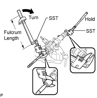
Using SST, install the steering rack end sub-assembly (RH side).
- SST
- 09922-10010
- Torque:
- 72 N*m { 736 kgf*cm, 53 ft.*lbf }
Note
-
Use SST 09922-10010 following the direction shown in the illustration.
-
Use a torque wrench with a fulcrum length of 345 mm (13.58 in.).
Tech Tips
Using SST, hold the steering rack and install the steering rack end sub-assembly.
-
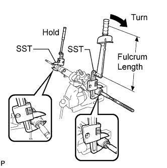
Using SST, install the steering rack end sub-assembly (LH side).
- SST
- 09922-10010
- Torque:
- 72 N*m { 736 kgf*cm, 53 ft.*lbf }
Note
-
Use SST 09922-10010 following the direction shown in the illustration.
-
Use a torque wrench with a fulcrum length of 345 mm (13.58 in.).
-
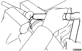
Using a brass bar and a hammer, stake the 2 claw washers.
Note
Avoid any impact to the steering rack.
-
-
INSTALL STEERING RACK BOOT NO.2
-
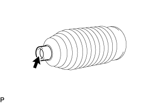
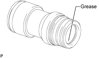
Apply silicon grease to the inside of the small opening of the steering rack boot No.2.
-
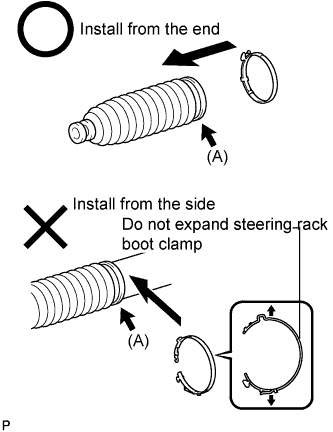
Temporarily install a new steering rack boot No.2 clamp to the large opening of the steering rack boot No.2 at the position shown by arrow (A).
Note
-
Use a new steering rack boot No.2 clamp.
-
Do not expand the steering rack boot No.2 clamp more than necessary for installation.
-
Do not deform the steering rack boot No.2 clamp.
-
Tightening force of the steering rack boot No.2 clamp becomes uneven if it is installed after being expanded as shown in the illustration. As a result, rust is caused by water entering from the clearance between the boot and rack housing, causing a malfunction.
-
Use only the supply parts which are applicable to the vehicle to secure the boot.
Tech Tips
After disengaging the claw of a new steering rack boot No.2 clamp, temporarily install it from the end without expanding the clamp diameter more than necessary.
-
-
Install the rack boot No.2 to the groove on the rack housing.
Note
-
Be careful not to damage or twist the boot.
-
Do not damage the steering rack boot No.2.
-
Ensure that the steering rack boot No.2 clamp is installed before installing the steering rack boot No.2 to the rack housing.
-
-
-
INSTALL STEERING RACK BOOT NO.1
Tech Tips
Perform the same procedure as for the steering rack boot No.2.
-
INSTALL STEERING RACK BOOT NO.2 CLAMP
-
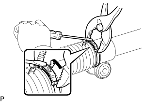
Using pliers and a screwdriver, install the steering rack boot No.2 clamp.
Note
-
Be careful not to damage the steering rack boot.
-
Do not twist the steering rack boot.
-
-
-
INSTALL STEERING RACK BOOT NO.1 CLAMP
Tech Tips
Perform the same procedure as for the steering rack boot No.2 clamp.
-
INSTALL STEERING RACK BOOT CLIP
-
Using pliers, install the 2 boot clips.
-
Using SST, turn the pinion and check that the rack boots expand and contract smoothly.
- SST
- 09616-00011
-
-
INSTALL TIE ROD END SUB-ASSEMBLY LH
-
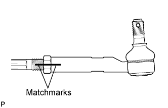
Install the lock nut and the tie rod sub-assembly LH to the rack end sub-assembly until the matchmarks are aligned.
Tech Tips
After adjusting toe-in, torque the lock nut.
-
-
INSTALL TIE ROD END SUB-ASSEMBLY RH
Tech Tips
Perform the same procedure as for the LH side.
-
INSTALL STEERING RIGHT TURN PRESSURE TUBE
-
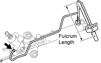
Using a union nut wrench, install the steering right turn pressure tube.
- Torque:
- 23 N*m { 232 kgf*cm, 17 ft.*lbf }
Note
Use a torque wrench with a fulcrum length of 300 mm (11.81 in.).
-
-
INSTALL STEERING LEFT TURN PRESSURE TUBE
-
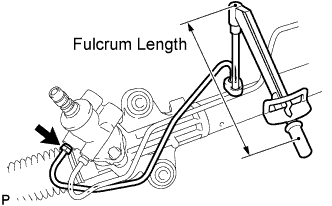
Using a union nut wrench, install the steering left turn pressure tube.
- Torque:
- 23 N*m { 232 kgf*cm, 17 ft.*lbf }
Note
Use a torque wrench with a fulcrum length of 300 mm (11.81 in.).
-