STEERING GEAR DISASSEMBLY

-
REMOVE STEERING LEFT TURN PRESSURE TUBE
-
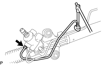
Using a union nut wrench, remove the steering left turn pressure tube.
-
-
REMOVE STEERING RIGHT TURN PRESSURE TUBE
-
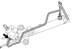
Using a union nut wrench, remove the steering right turn pressure tube.
-
-
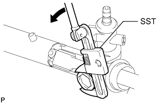
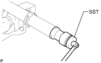
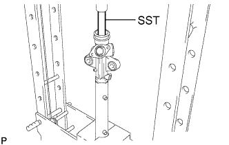
FIX POWER STEERING LINK ASSEMBLY
-
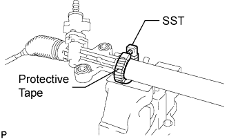
Using SST, secure the power steering link assembly.
- SST
- 09612-00012
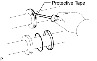
Tech Tips
Tape the SST before use.
-
-
REMOVE TIE ROD END SUB-ASSEMBLY LH
-
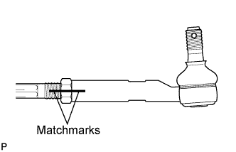
Put matchmarks on the tie rod end sub-assembly LH and the steering rack end sub-assembly.
-
Loosen the lock nut, and remove the tie rod end sub-assembly LH and the lock nut.
-
-
REMOVE TIE ROD END SUB-ASSEMBLY RH
Tech Tips
Perform the same procedure as for the LH side.
-
REMOVE STEERING RACK BOOT CLIP
-
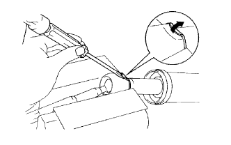
Using pliers, remove the 2 steering rack boot clips.
-
-
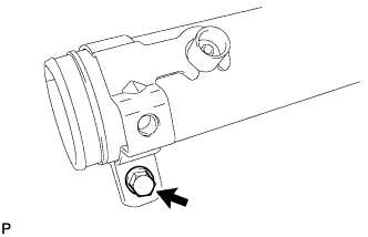
REMOVE STEERING RACK BOOT NO.2 CLAMP
-
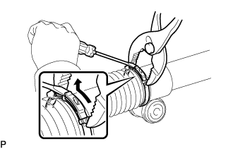
Using pliers and a screwdriver, remove the steering rack boot No.2 clamp as shown in the illustration.
Note
Be careful not to damage the boot.
-
-
REMOVE STEERING RACK BOOT NO.1 CLAMP
Tech Tips
Perform the same procedure as for the steering rack boot No.2 clamp.
-
REMOVE STEERING RACK BOOT NO.2
-
REMOVE STEERING RACK BOOT NO.1
-
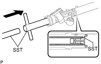
REMOVE STEERING RACK END SUB-ASSEMBLY
-
Using a screwdriver and a hammer, unstake the RH and LH claw washers.
Note
Avoid any impact to the steering rack.
-
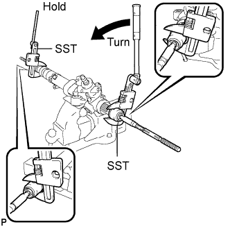
Using SST, remove the steering rack end sub-assembly (LH side) and the claw washer.
- SST
- 09922-10010
Note
Use SST 09922-10010 following the direction shown in the illustration.
-
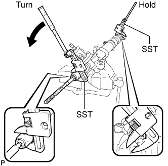
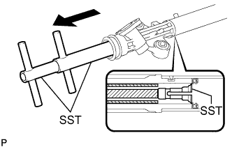
Using SST, remove the steering rack end sub-assembly (RH side) and the claw washer.
- SST
- 09922-10010
Note
Use SST 09922-10010 following the direction shown in the illustration.
Tech Tips
Using SST, hold the rack and remove the steering rack end sub-assembly.
-
-
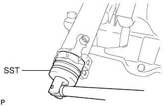
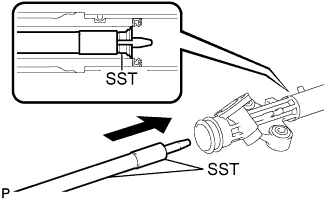
REMOVE POWER STEERING RACK GUIDE
-
Using SST, remove the power steering rack guide spring cap nut.
- SST
- 09922-10010
Note
Use SST 09922-10010 following the direction shown in the illustration.
-
Using a straight hexagon wrench 24 mm (0.94 in.), remove the power steering rack guide spring cap.
-
Remove the compression spring and the power steering rack guide.
-
Remove the rack guide seat from the power steering rack guide.
-
-
REMOVE POWER STEERING CONTROL VALVE ASSEMBLY
-
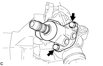
Remove the 2 bolts and the power steering control valve assembly.
-
Remove the gasket.
-
-
REMOVE CYLINDER END STOPPER
-
Body type narrow:
-
Loosen the bolt.
-
Using SST, remove the cylinder end stopper from the rack housing.
- SST
- 09631-20120
-
Remove the tube support retainer.
-
-
Body type wide:
-
Using SST, remove the cylinder end stopper and the spacer from the rack housing.
- SST
- 09631-20120
-
Using a screwdriver, remove the O-ring from the cylinder end stopper.
Note
Be careful not to damage the cylinder end stopper.
Tech Tips
Tape the screwdriver tip before use.
-
Using a screwdriver, remove the bushing from the cylinder end stopper.
Note
Be careful not to damage the cylinder end stopper.
Tech Tips
Tape the screwdriver tip before use.
-
-
-
REMOVE POWER STEERING RACK
-
Temporarily install the service bolt to the power steering rack.
Recommended service bolt Thread diameter 14 mm (0.55 in.) Thread pitch 1.5 mm (0.059 in.) -
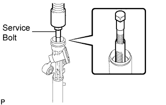
Using a press, remove the power steering rack.
-
Remove the cylinder end stopper oil seal from the power steering rack.
-
Using a screwdriver, remove the oil seal and the O-ring from the power steering rack.
Note
Be careful not to damage the oil seal groove on the power steering rack.
Tech Tips
Tape the screwdriver tip before use.
-
-
REMOVE POWER STEERING CYLINDER TUBE OIL SEAL
-
Install SST (09612-07120) to SST (09612-07210).
- SST
- 09612-70100 ( 09612-07120, 09612-07210 )
Note
-
Lightly apply MP grease to the tip of SST (09612-07230) and inside of SST (09612-07210 and 09612-07120) before use.
-
Completely install SST (09612-07120) to SST (09612-07210) to prevent damage to the inside of the rack housing.
-
Insert SST (09612-07210) into the rack housing at a slant until it comes in contact with the power steering cylinder tube oil seal. Install SST (09612-07220) to SST (09612-07210).
- SST
- 09612-70100 ( 09612-07120, 09612-07210, 09612-07220 )
Note
Do not damage the inside of the power steering rack housing.
-
Hold SST, (09612-70220) and pull SST (09612-07210) to position SST (09612-07120) to the inside of the rack housing.
- SST
- 09612-70100 ( 09612-07120, 09612-07210, 09612-07220, 09612-07230 )
Tech Tips
Ensure that SST (09612-07120) is positioned at the chamfered part between the power steering cylinder tube oil seal and the rack housing.
-
Install SST (09612-07240) to SST (09612-07230). Insert the tip of SST (09612-07230) into the service hole of SST (09612-07120) in the rack housing.
- SST
- 09612-70100 ( 09612-07120, 09612-07230, 09612-07240 )
Note
-
Ensure that SST (09612-07240) is installed to prevent damage to SST (09612-07120).
-
Do not damage the inside of the rack housing.
-
Install SST (09951-07150) to SST (09612-07230). Using a press, remove the power steering cylinder tube oil seal.
- SST
- 09612-70100 ( 09612-07120, 09612-07230, 09612-07240 )
- 09950-70010 ( 09951-07150 )
Note
Do not damage the rack housing.
Tech Tips
Change SST (09951-07150) for another, from the set, with different length as needed.
-