STEERING COLUMN ASSEMBLY REASSEMBLY

-
INSTALL STEERING LOCK ACTUATOR ASSEMBLY (w/ Smart Entry and Start System)
Tech Tips
When replacing the steering lock actuator assembly, refer to the Service Bulletin.
-
Temporarily install the steering lock actuator assembly with a new tapered-head bolt.
Note
Be sure to use a new tapered-head bolt.
-
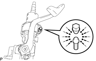
Tighten the tapered-head bolt until the bolt head breaks off.
-
-
INSTALL STEERING COLUMN CLAMP UPPER NO.2
-
INSTALL IGNITION OR STARTER SWITCH ASSEMBLY (w/o Smart Entry and Start System)
-
Install the ignition or starter switch assembly to the steering column upper bracket assembly with the 2 screws.
-
-
INSTALL UN-LOCK WARNING SWITCH ASSEMBLY (w/o Smart Entry and Start System)
-
Automatic transmission:
-
Connect the key interlock solenoid terminals to the un-lock warning switch assembly connector.
-
-
Slide the un-lock warning switch assembly and engage the 2 claws to install the assembly to the steering column upper with switch bracket assembly.
-
Connect the un-lock warning switch assembly connector to the ignition or starter switch assembly.
-
Manual transmission:
-
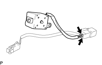
Secure the un-lock warning switch assembly wire harness to the steering column upper bracket assembly with a new clamp as shown in the illustration.
Note
Do not overtighten the clamp when securing the wire harness as the wire harness could be cut.
-
-
Automatic transmission:
-
Install the key inter lock solenoid to the steering column upper bracket assembly with the 2 screws.
-
-
-
INSTALL IGNITION SWITCH LOCK CYLINDER ASSEMBLY (w/o Smart Entry and Start System)
-
Make sure the ignition switch lock cylinder assembly is in the ACC position.
-
Install the ignition switch lock cylinder assembly to the steering column upper with switch bracket assembly.
-
-
INSPECT STEERING LOCK OPERATION (w/o Smart Entry and Start System)
-
Check that the steering lock mechanism is activated when the key is removed.
-
Check that the steering lock mechanism is deactivated when the key is inserted and turned to the ACC position.
Tech Tips
If there is any abnormality, replace the ignition switch lock cylinder assembly.
-
-
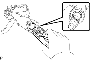
INSTALL STEERING MAIN SHAFT ASSEMBLY (w/o Smart Entry and Start System)
-
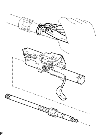
Using a snap ring expander, install a new steering main shaft snap ring (inner side) to the steering main shaft assembly.
-
Install the steering main shaft assembly to the steering column tube.
-
Secure the steering column tube in a vise. Insert aluminum plates between the steering column tube and the vise to prevent damage.
Note
Do not overtighten the vise.
-
Using a snap ring expander, install a new steering main shaft snap ring (outer side) to the steering main shaft assembly.
-
-
INSTALL STEERING MAIN SHAFT BEARING (w/o Smart Entry and Start System)
-
Hold the steering column tube in a vise between aluminium plates.
Note
Do not apply excessive force to the steering column tube bracket when holding the steering column tube in a vise.
-
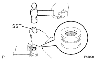
Install a new steering main shaft bearing to the steering column tube using SST and a hammer.
- SST
- 09612-22011
-
-
INSTALL STEERING COLUMN UPPER W/ SWITCH BRACKET ASSEMBLY (w/o Smart Entry and Start System)
-
Temporarily install the steering column upper with switch bracket assembly and steering column upper clamp with 2 new tapered-head bolts.
-
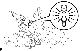
Tighten the 2 tapered-head bolts until the bolt heads break off.
-
-
INSTALL KEY CYLINDER LIGHT ASSEMBLY (w/o Smart Entry and Start System)
-
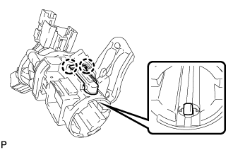
Engage the 2 claws and install the key cylinder light assembly to the steering column upper bracket assembly.
-
-
INSTALL STEERING INTERMEDIATE SHAFT NO.2
-
Align the matchmarks on the intermediate shaft assembly No.2 and the steering main shaft assembly.
-
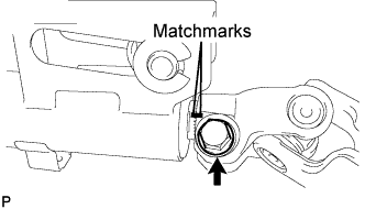
Install the bolt.
- Torque:
- 36 N*m { 367 kgf*cm, 27 ft.*lbf }
-